
Method for acquiring signals

a signal acquisition and signal technology, applied in the field of signal acquisition, can solve the problems of increasing the storage and communication requirements of the running time, increasing the volume of data to be transmitted, and not having the needed signals in the measurement file, so as to reduce the number of signals that are actually to be measured and reduce the data volume of the measurement

Inactive Publication Date: 2018-07-12
ROBERT BOSCH GMBH
View PDF2 Cites 0 Cited by
  • Summary
  • Abstract
  • Description
  • Claims
  • Application Information

AI Technical Summary

Benefits of technology

The present invention relates to a method for acquiring signals from a control unit. The method involves creating a program dependency graph, defining a set of signals to measure, assigning nodes to the signals, measuring the signals, and calculating dependent signals based on the measured signals. This method reduces the number of signals measured and ensures that all relevant signals are available for analysis. The measured signals can be stored in a record for later use or in a nonvolatile memory for continued calculation after power interruption. The technical effect of this invention is to efficiently reduce the number of signals measured and to enable the efficient analysis of all relevant signals.

Problems solved by technology

Consequently, first of all, the storage and communications requirement for the running time increases, and secondly, the volume of data to be transmitted also increases.
Thus, in the analysis of the measurements, it may occur that needed signals are not contained in the measurement file.
This generates considerable expenditure for the measuring, as also for the subsequent communication and the delayed availability.

Method used


Image

  • Method for acquiring signals
  • Method for acquiring signals
  • Method for acquiring signals

Examples


Embodiment Construction

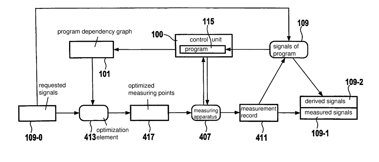
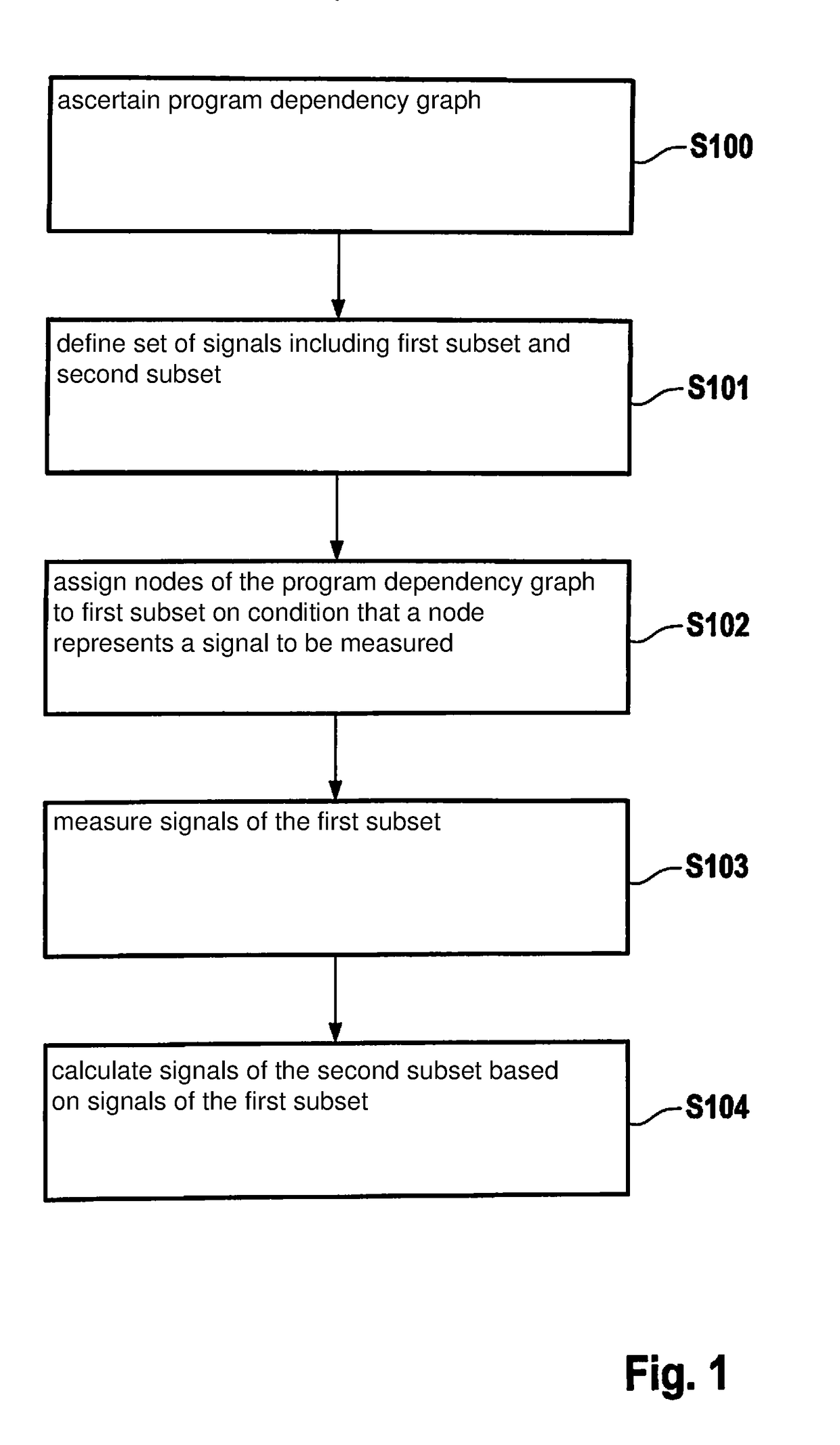
[0021]FIG. 1 shows a block diagram of an example method for acquiring signals of a control unit. The control unit is, for example, a control unit for engine control, which may potentially acquire a plurality of measured variables. A program of the control unit is used for evaluating and processing these measured variables further. In a plurality of computational steps, the program calculates one or more output signals from a plurality of input signals.

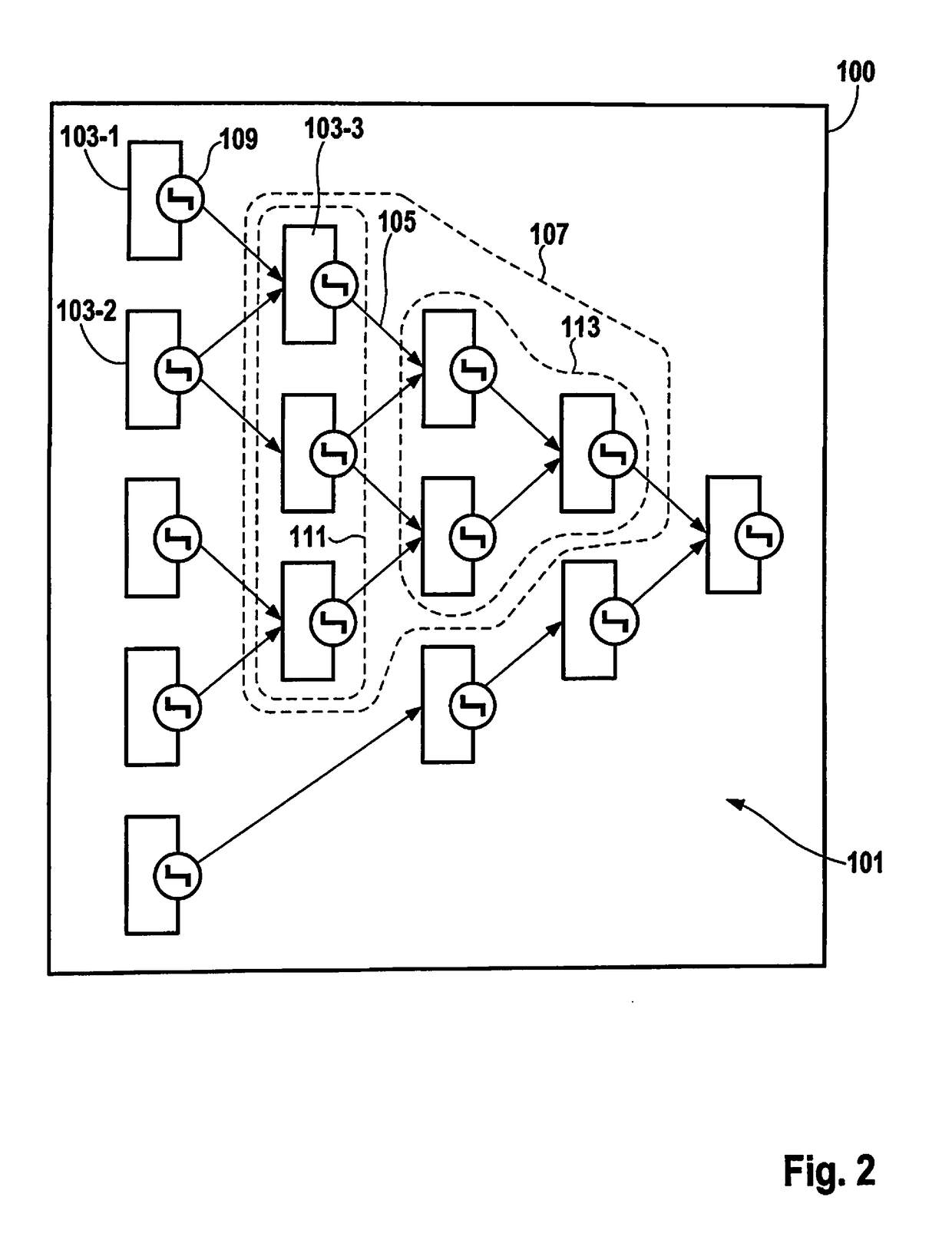
[0022]Consequently, each computational step generates, as an output, a further internal signal, which is processed further, using a further computational step.

[0023]In general, the control unit may be used for controlling any other device. The program of the control unit may be represented by a program dependency graph (program dependence graph). The determination of signals of the control unit, to be acquired, is carried out on the basis of this program dependency graph. The signals, which must be known for the calculation of a given ...


PUM


Abstract

A method for acquiring signals of a control unit, including the steps of ascertaining a program dependency graph from a program of the control unit, the nodes of the program dependency graph being the computational steps of the program, from which signals are obtained, and whose segments are the data and / or control dependencies between the computational steps; defining a set of signals, which includes a first subset of signals to be measured and a second subset of dependent signals; assigning nodes to the first subset on condition that a node represents a signal to be measured, if a node is situated at an incoming segment of the node, outside of the set of signals; measuring the signals of the first subset; and calculating the signals of the second subset on the basis of the measured signals of the first subset.

Description

CROSS REFERENCE[0001]The present application claims the benefit under 35 U.S.C. § 119 of German Patent Application No. DE 102017200161.5 filed on Jan. 9, 2017, which is expressly incorporated herein by reference in its entirety.FIELD[0002]The present invention relates to a method for acquiring signals of a control unit, as well as to a corresponding control unit.BACKGROUND INFORMATION[0003]In order to be able to reproduce effects, which occur in a control unit, internal signals are recorded during the running time of the control unit. These signal characteristics may then be visualized and evaluated with the aid of analysis software.[0004]In this context, the number of logged signals or variables is limited, since the storage requirement increases linearly with the number of signals to be measured. Consequently, first of all, the storage and communications requirement for the running time increases, and secondly, the volume of data to be transmitted also increases. Therefore, only a...

Claims


Application Information

Patent Timeline
Patent Type & Authority Applications(United States)
IPC IPC(8): G01R19/25G06F13/36
CPCG01R19/2509G06F13/36G06F8/22
Inventor QUANTE, JOCHEN
Owner ROBERT BOSCH GMBH
Learn More