

Reduced footprint collimator device to focus light beam over length of optical path
a collimator device and footprint reduction technology, applied in the direction of optical elements, coatings, instruments, etc., can solve the problems of reducing the beam power at the receptor, limiting the number of receptors, and reducing the overall instrument size, so as to reduce the footprint, reduce the stray light reflection, and the effect of reducing the footprin
Active Publication Date: 2018-07-12
MACCAL CO INC
View PDF7 Cites 2 Cited by
- Summary
- Abstract
- Description
- Claims
- Application Information
AI Technical Summary
Benefits of technology
The invention is a small optical beam collimator that reduces stray light reflections and allows for easier alignment of the light beam with the receiving photomultipliers. It achieves these goals while maintaining the beam power and aligning the beam over the length of the optical path. This results in a smaller overall instrument design.
Problems solved by technology
The problem is that the farther the photomultiplier is from the laser source the lower the beam power is at the receptor.
This required bend radius forces a much larger footprint which makes the overall instrument larger or limits the number of receptors.
Method used
View moreImage
Smart ImageViewing Examples

Examples
Embodiment Construction
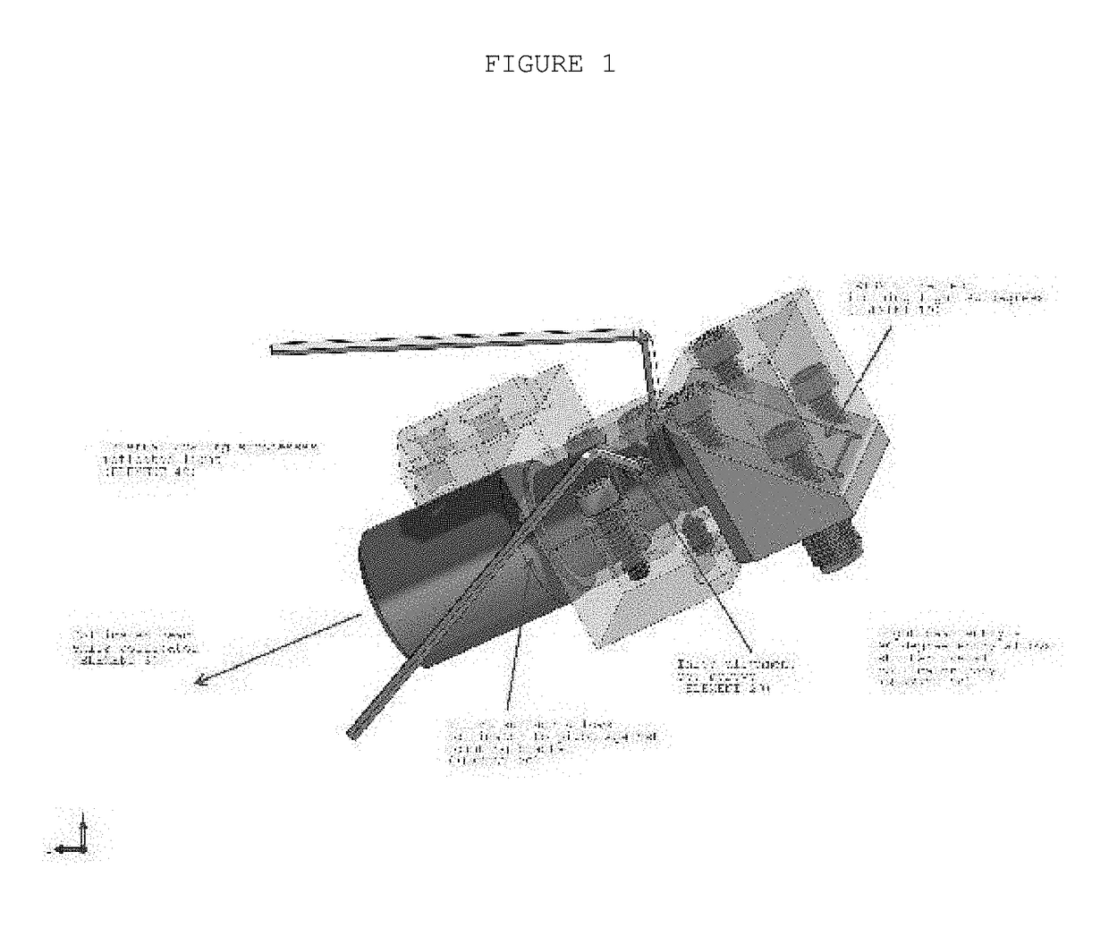
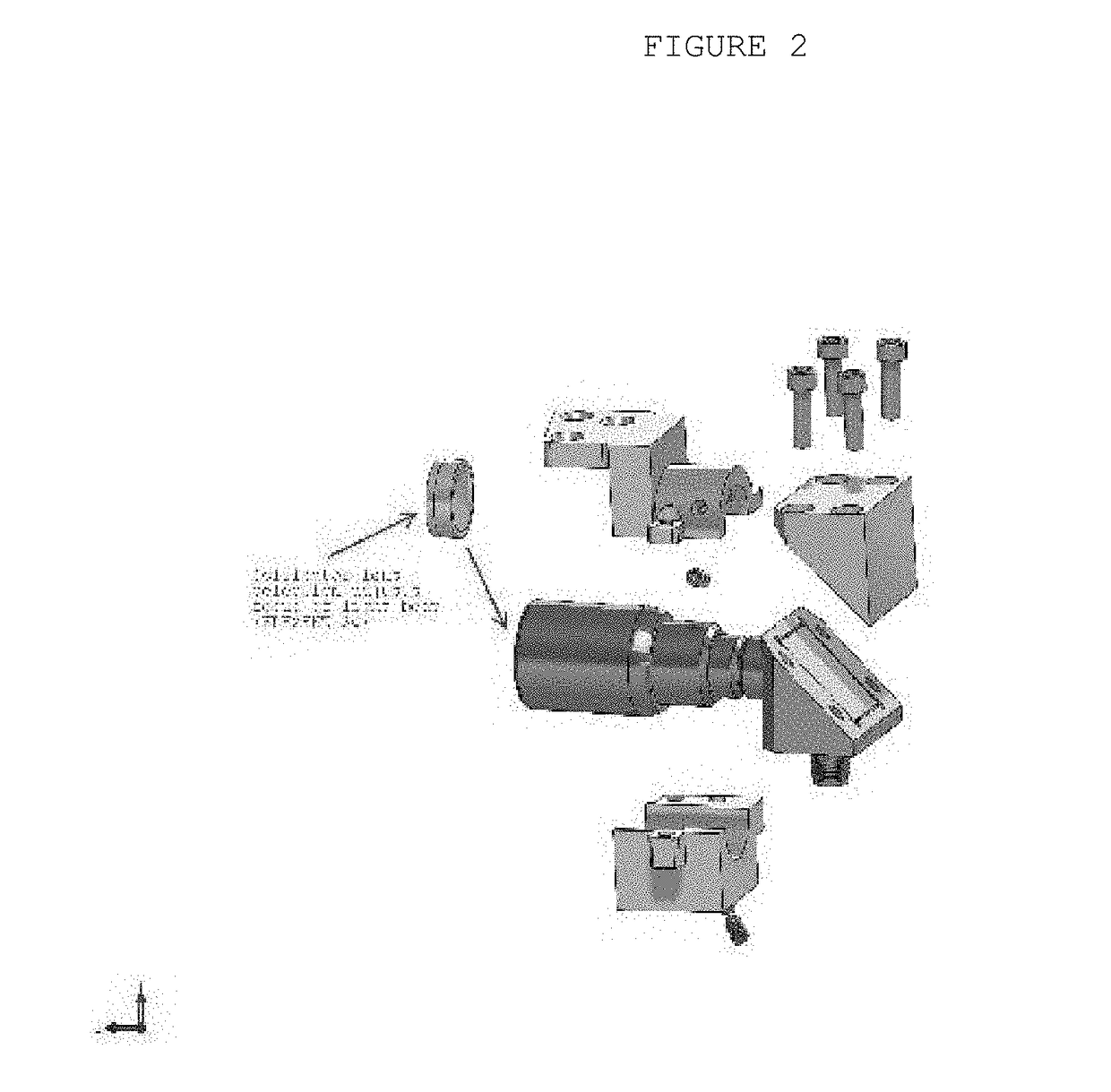
[0025]FIG. 1 is a right perspective view of a complete collimator assembly 10 showing mounting and adjustment capability.
[0026]Since other modifications and changes varied to fit particular operating requirements and environments will be apparent to those skilled in the art, the invention is not considered limited to the example chosen for purposes of disclosure, and covers all changes and modifications which do not constitute departures from the true spirit and scope of this invention.
[0027]Having thus described the invention, what is desired to be protected by Letters Patent is presented in the subsequently appended claims.
Login to View More PUM
| Property | Measurement | Unit |
|---|---|---|
| bend radius | aaaaa | aaaaa |
| length | aaaaa | aaaaa |
| optical | aaaaa | aaaaa |
Abstract
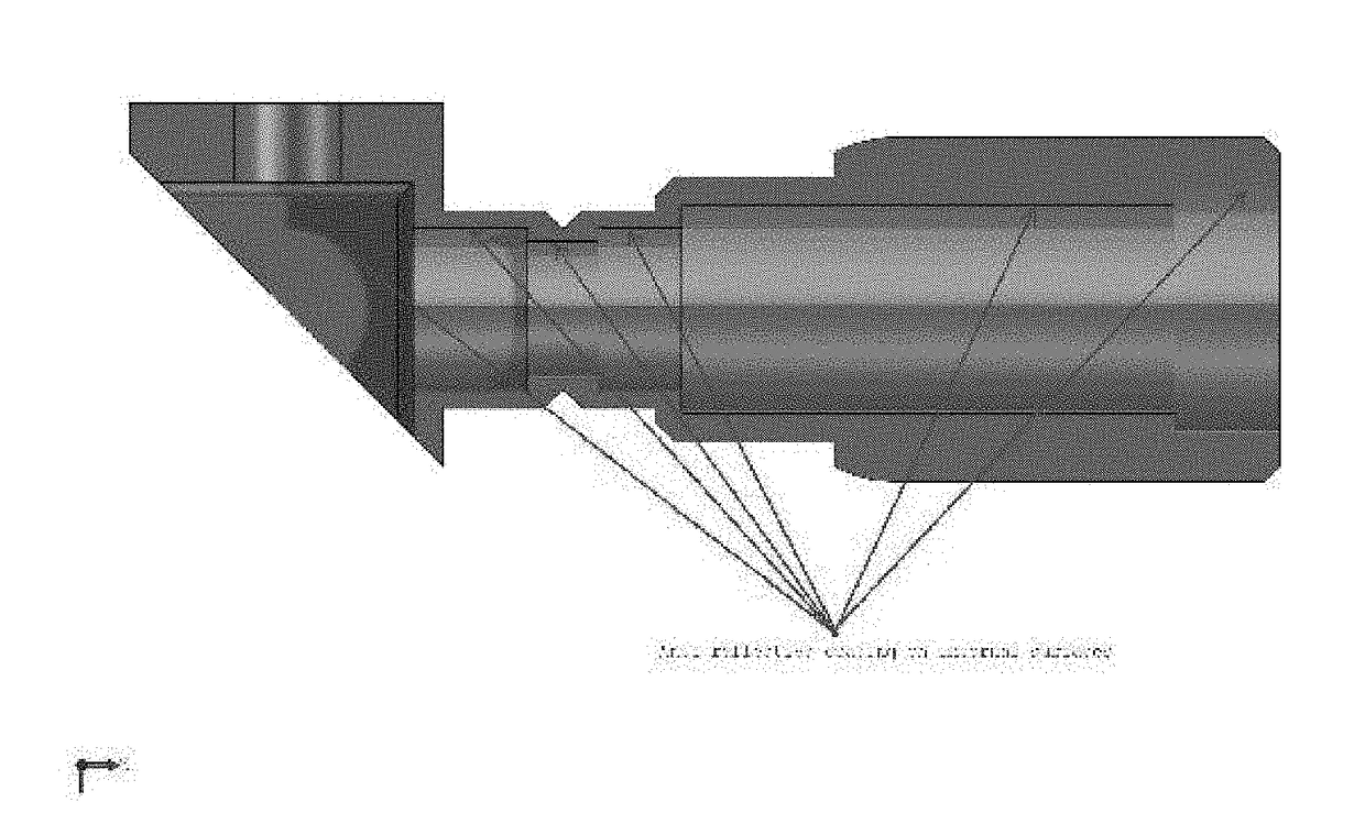
A reduced footprint collimator device to focus light beam over length of optical path for use in an optical cytometry device or other optical instrument where a focused beam of light is passed through a test medium and then sampled by a photomultiplier or multiple photomultipliers for analysis. This device provides alignment and focus of that beam and collimation along the entire beam path. In addition in order to reduce the overall footprint of the beam path this device uses a precision coated prism to redirect the optical path perpendicular to the entering optical beam. The reduced footprint collimator device to focus light beam over length of optical path generally includes a reduced footprint 90 degree collimator which allows light beam collimation, beam path alignment, selectable beam focal distance, and reduces stray light reflections all in a minimal footprint.an These features allows for a smaller overall instrument design.
Description
RELATED APPLICATIONS[0001]The present application is a continuation application of U.S. provisional patent application Ser. No. 62 / 179,578, filed May 2, 2016, for REDUCED FOOTPRINT COLLIMATOR DEVICE TO FOCUS LIGHT BEAM OVER LENGTH OF OPTICAL PATH, by Robert Duncan, Michael Hall, James Nguyen, included by reference herein and for which benefit of the priority date is hereby claimed.FIELD OF THE INVENTIONBackground of the Invention[0002]For flow cytometry applications, laser beams of various wavelengths of light are directed through a chamber filled with the sample to be tested. The samples absorb some wavelengths while passing others. The laser beams which are not absorbed pass out of the chamber and typically are directed into a fiber optic cable for connection to a device which directs the beams through various filters into photo receptors (photomultipliers) which convert the light signals into electrical signals for computer analysis. The problem is that the farther the photomulti...
Claims
Login to View More Application Information
Patent Timeline
 Patent Type & AuthorityApplications(United States)
IPC IPC(8): G02B27/30G02B1/11G01N15/14
CPCG02B27/30G02B1/11G01N15/1434G01N15/1459
InventorDUNCAN, ROBERTNGUYEN, JAMESHALL, MICHAEL
OwnerMACCAL CO INC