Apparatus for displaying medical image data of a body part

a technology body parts, applied in the field of apparatus for displaying medical image data of body parts, can solve the problems of substantially larger reading time, similar problems, and difficulty in assessing the larger amount of data in a comparable time without missing, and achieve the effect of improving techniqu

Active Publication Date: 2018-07-19
KONINKLJIJKE PHILIPS NV
View PDF3 Cites 5 Cited by
  • Summary
  • Abstract
  • Description
  • Claims
  • Application Information

AI Technical Summary

Benefits of technology

[0007]It would be advantageous to have an improved technique for displaying medical image data of a body part.
[0020]In this manner, the apparatus displays all of the subsets of medical image data (e.g. plurality of X-ray images), but does so as a function of, or in other words based on, a weighting factor for each of the subsets of medical image data (e.g. X-ray images) that is derived from a measure of information content for that subset of medical image data (e.g. X-ray image). In other words, the clinician is able to look at or review all of the subsets of medical image data (e.g. X-ray images or parts of an X-ray image) that have been taken, using their skill and knowledge to determine if a further examination is required, but by displaying the subsets of medical image data (e.g. plurality of X-ray images) as a function of the weighting factors the clinician can focus on those subsets of medical image data (e.g. X-ray images) that contain the most information. Therefore, the clinician can review the subsets of medical image data (e.g. X-ray images) more effectively in terms of being able to identify anomalies, and can also do this in a more timely manner. 3D imaging of the body part, such as a breast, is enabled with a potential reduction in the time needed by a clinician to review the data.
[0023]By this way, for example a cine loop of subsets of medical image data (e.g. X-ray images) can be displayed over a predetermined period of time, and where those subsets of medical image data (e.g. X-ray images) with more information content are shown for a longer period of time than those subsets of medical image data (e.g. X-ray images) with less information content. In other words, a time-between-frames can be determined for presenting the subsets of medical image data (e.g. X-ray images) as a cine-loop. In this manner, a clinician is more effectively able to determine if further analysis is warranted, and can do this in a timely manner. To put it another way, an optimal display time for each slice in a volume stack, or for each region of a slice, can be computed.
[0028]In this manner, a reduced number of subsets of medical image data (e.g. X-ray images) of variable slab thickness can be determined, each having substantially the same information content and as such the clinician can spend, or expect to spend, the same time reviewing each.
[0041]In this manner, those subsets of medical image data (e.g. X-ray images) with little image content can be combined together into one or a number of a combined images (e.g. combined X-ray image(s)) with an increased information content, thereby reducing the total number of images and therefore speeding up the review process, and also the clinician will better be able to determine from the combined image whether there is for example an abnormality because the image or information content for that combined image has been increased. In other words, in an example the plurality of images is transformed into a plurality of combined images, where the number of combined images is less than the number of images and each combined image contains roughly the same amount of information. In this manner, the clinician is provided with fewer frames to inspect and can expect to spend approximately the same amount of time reviewing each frame, because the combined images (slabs of variable thickness) each have substantially the same measure of information content. In an example, the plurality of combined images is displayed.
[0042]In other words, images or slices (e.g. X-ray images) are combined in slabs of variable slice thickness, which is computed such that each slab contains the same amount of image information or information content and has the same weighting factor. Put another way, in an example several neighbouring slices in a stack are combined to form a slab, such that the entropy of each slab is approximately equal. The clinician can then view a reduced number of images (e.g. X-ray images) in assessing the full image set, thereby taking less time. In this manner, each image can be shown or viewed for the same length as time as other images, because each contains approximately the same amount of information. According to another aspect, there is provided a computer program element controlling apparatus as previously described which, in the computer program element is executed by processing unit, is adapted to perform the method steps as previously described. According to another aspect, there is provided a computer readable medium having stored computer element as previously described.Advantageously, the benefits provided by any of the above aspects and examples equally apply to all of the other aspects and examples and vice versa.The above aspects and examples will become apparent from and be elucidated with reference to the embodiments described hereinafter.

Problems solved by technology

Similar issues arise when viewing volumetric 3-D X-ray images other than tomosynthesis volume stacks, such as for example CT 3D volume stacks and magnetic resonance (MR) volume stacks.
The additional amount of data slows down the diagnostic reading of the acquired X-ray image data when transitioning from 2D to 3D screening, resulting in substantially larger reading times. Within a screening scenario it is therefore difficult to assess the larger amount of data in a comparable time without missing diagnostically relevant structures.
Similar issues relate to the viewing of other medical data, such as that acquired by CT systems, Magnetic Resonance systems and Ultrasound systems.
Furthermore, in relation to a single medical image, the clinician can also miss diagnostically relevant structures.

Method used


Image

  • Apparatus for displaying medical image data of a body part
  • Apparatus for displaying medical image data of a body part
  • Apparatus for displaying medical image data of a body part

Examples


Embodiment Construction

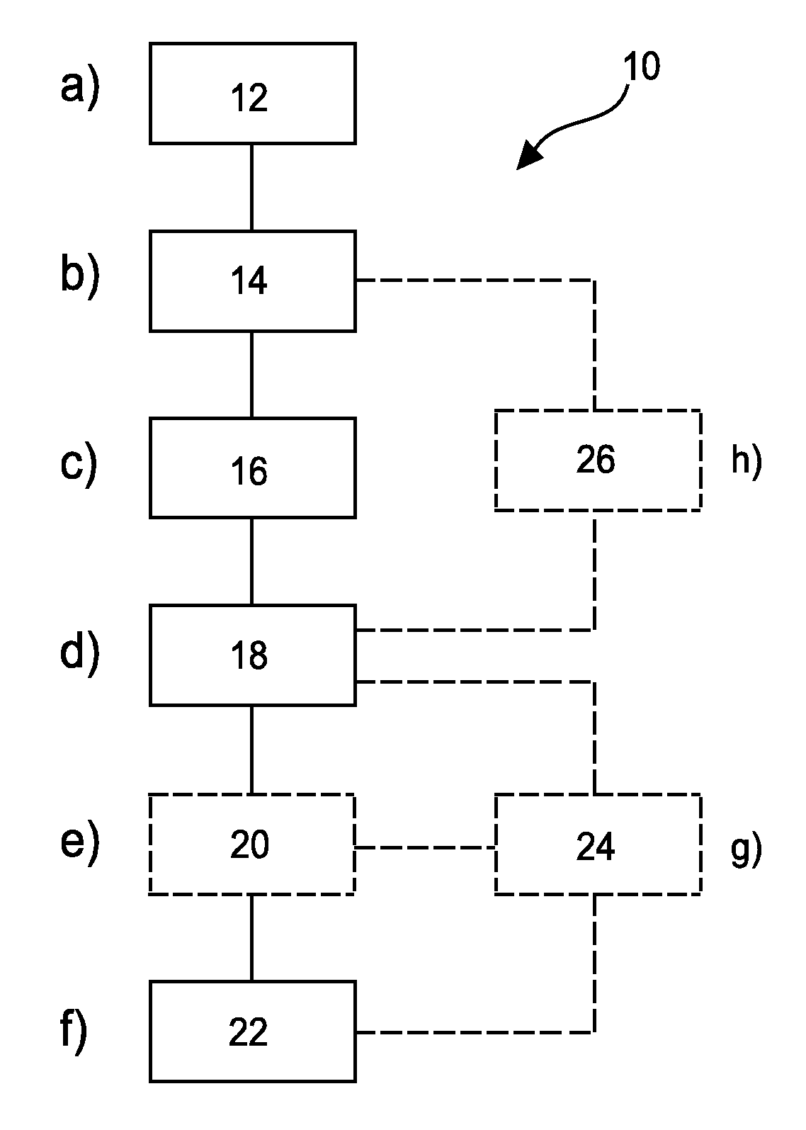
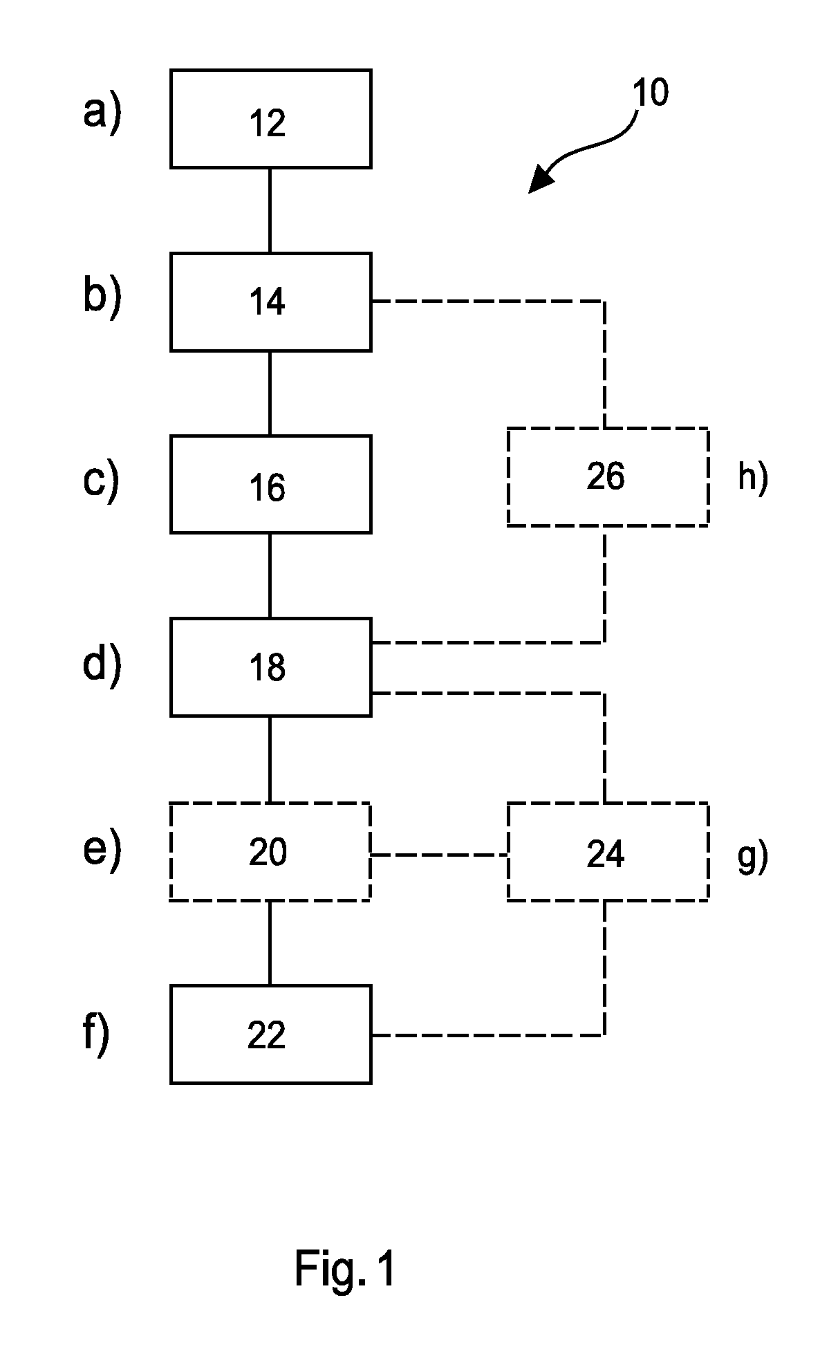
[0052]FIG. 1 shows a method 10 for displaying medical image data of a body part in its basic steps. The method comprises the following:

[0053]In a providing step 12, also referred to as step a), medical data of a body part is provided.

[0054]In a first determining step 14, also referred to as step b), subsets of medical image data from the medical data are determined.

[0055]In a second determining step 16, also referred to as step c), a plurality of measures of information content for the subsets of medical image data is determined, wherein a measure of information content is associated with a subset of medical image data.

[0056]In a third determining step 18, also referred to as step d), a plurality of weighting factors for the subsets of medical image data is determined, wherein a weighting factor is associated with a subset of medical image data and the weighting factor is determined as a function of the measure of information content for that subset of medical image data.

[0057]In an...


PUM


Abstract

The present invention relates to an apparatus for displaying medical image data of a body part. It is described to provide (12) medical data of a body part, and subsets of medical image data from the medical data are determined (14). A plurality of measures of information content for the subsets of medical image data is determined (16), wherein a measure of information content is associated with a subset of medical image data. A plurality of weighting factors for the subsets of medical image data is determined (18), wherein a weighting factor is associated with a subset of medical image data and the weighting factor is determined as a function of the measure of information content for that subset of medical image data. Data representative of the subsets of medical image data is output (22) as a function of the plurality of weighting factors.

Description

FIELD OF THE INVENTION[0001]The present invention relates to an apparatus for displaying medical image data of a body part, to a medical system for displaying medical image data of a body part, and to a method for displaying medical image data of a body part, as well as to a computer program element and a computer readable medium.BACKGROUND OF THE INVENTION[0002]X-ray tomosynthesis is a technique that creates 3-D image representations. For example, when applied to mammography 3-D image representations of the breast can be created. A 3-D image representation is created from individual 2-D images, where the 2-D images are referred to as a stack. An individual 2-D image is referred to as a slice. Digital breast tomosynthesis both enables 3D imaging of the breast and offers the potential of increased cancer detection rates at reduced recall rates compared to standard 2D mammography screening. In a standard 2D mammography examination, a radiologist generally has to review four individual...

Claims


Application Information

Patent Timeline
Patent Type & Authority Applications(United States)
IPC IPC(8): A61B6/00A61B5/055A61B6/02A61B8/00G06K9/46G06K9/52G06T15/08G16H30/40G16H40/63G06V10/42G06V10/50G16H30/20
CPCA61B6/463A61B5/055A61B6/025A61B6/466A61B6/502A61B6/5235A61B8/463G06K9/4642G06K9/52G06T15/08G16H30/40G16H40/63G06K2209/051G06T2207/10116G06T2207/20221G06T2207/30068A61B6/486G06T5/50G16H30/20G06V10/50G06V10/462G06V10/42G06V2201/031
Inventor ERHARD, KLAUS
Owner KONINKLJIJKE PHILIPS NV
Why Eureka
Try Eureka