Fan impeller and radiator fan module

a technology for radiator fans and impellers, which is applied in the direction of machines/engines, mechanical equipment, liquid fuel engines, etc., can solve the problems of negative impact on the flow behaviour of radiator fans and high level of undesirable noise generation

Active Publication Date: 2018-07-19
BROSE FAHRZEUGTEILE GMBH & CO KG +1
View PDF6 Cites 3 Cited by
  • Summary
  • Abstract
  • Description
  • Claims
  • Application Information

AI Technical Summary

Benefits of technology

[0017]In an embodiment according to the invention, the flow fins and the outer ends of the fan impeller blades may be arranged obliquely to the circumferential direction of the fan impeller outer ring. In this case, the flow fins and the outer ends of the fan impeller blades may be arranged in the same oblique position relative to the circumferential direction or in a different oblique position relative to the circumferential direction of the fan impeller outer ring. The angle of the oblique position of the flow fin or the blade has an effect on the flow topology in the blade tip region.
[0018]According to an embodiment of the invention, the fan impeller is e.g. integrally formed as an injection-moulded part. As a result, the fan impeller can be very simply and cost-effectively manufactured to have additional flow fins. In another embodiment according to the invention, the flow fins or a combination of the fan impeller outer ring and the flow fins are fastened to the rest of the fan impeller as a separate component. A combination of the fan impeller outer ring and the flow fins can be arranged on an existing fan impeller very simply by means of adhesive bonding or friction welding. Individual parts may for example be manufactured using 3D printing. Injection moulding is the most common manufacturing option for the complete part.

Problems solved by technology

The swirling gap flow works against the main flow, leading to a negative impact on the flow behaviour of the radiator fan module.
This defective flow sometimes leads to a very high level of undesirable noise being generated.

Method used


Image

  • Fan impeller and radiator fan module
  • Fan impeller and radiator fan module
  • Fan impeller and radiator fan module

Examples


Embodiment Construction

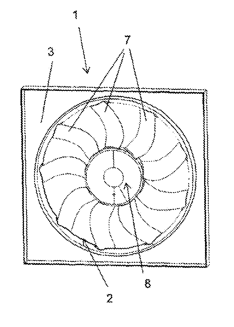
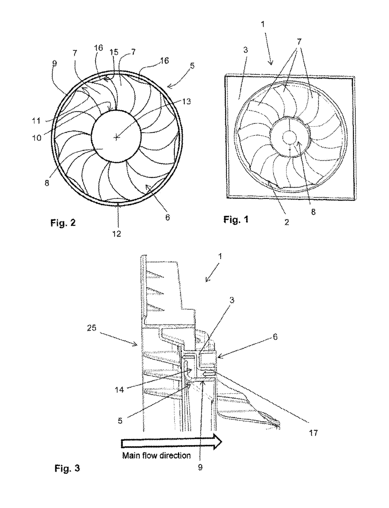
[0045]FIG. 1 is a perspective front view of a radiator fan module 1. The radiator fan module 1 comprises a frame 3, which has a substantially rectangular form in the example shown in FIG. 1. A recess or opening is provided within the frame 3, in which the fan impeller 2 comprising fan impeller blades 7 and a hub 8 is arranged. The fan impeller 2 is fastened to the frame 3 by means of mounting struts (not shown).

[0046]A fan impeller according to the invention described in the following with reference to FIGS. 2 to 6 can be used in such an example of a radiator fan module 1. The invention is, however, not restricted to the specific radiator fan module, as shown in FIG. 1.

[0047]Instead, the fan impeller according to the invention can be used in any suitable radiator fan module.

[0048]FIG. 2 is a purely schematic and highly simplified view of an embodiment of a fan impeller 5 according to the invention. In FIG. 2, the fan impeller 5 is shown from its front side 6, from which point air is...


PUM


Abstract

The invention relates to a fan impeller (5) for a radiator fan module (1) in a motor vehicle as well as to a radiator fan module, the fan impeller comprising: a hub (8), a shroud (9), a plurality of blades (7) that extend from the hub (8) outward and are connected to each other via the shroud (9), and a plurality of streamlining fins (16) which are located between the blades (7), on the bottom side (12) of the shroud (9).

Description

FIELD OF THE INVENTION[0001]The present invention relates to a fan impeller for a radiator fan module and to a radiator fan module comprising a fan impeller.TECHNICAL BACKGROUND[0002]Currently, radiator fan modules are used to cool the engine in motor vehicles. A radiator fan module typically consists of a fan impeller, in which a motor to drive the fan impeller is arranged, and a frame which comprises mounting struts for fastening the fan impeller.[0003]The fan impeller of a radiator fan module is generally designed to produce an air flow with which the heat generated by the engine of a motor vehicle is to be carried away. Radiator fan modules have what is known as a gap flow in addition to the main flow. The gap flow refers to the flow which forms between the fan impeller and the frame due to the pressure differential and which tends to swirl due to the rotation of the fan impeller. The swirling gap flow works against the main flow, leading to a negative impact on the flow behavio...

Claims


Application Information

Patent Timeline
Patent Type & Authority Applications(United States)
IPC IPC(8): F04D29/16F01P5/06F01P11/10F04D29/32F04D29/52F04D29/66
CPCF04D29/164F01P5/06F01P11/10F04D29/326F04D29/526F04D29/667F04D29/327
Inventor SPRINGER, NILSMAUSS, MICHAELKAMEIER, FRANKNA, GI-DON
Owner BROSE FAHRZEUGTEILE GMBH & CO KG
Why Eureka
Try Eureka