
Method for operating a mill train and a correspondingly embodied mill train

a mill train and embodied technology, applied in the direction of rolling mill control devices, manufacturing tools, profile control devices, etc., can solve the problems of affecting the operation of the mill train, etc., to achieve flexible working of the rolling stock, simple and reliable, and precise and reliable conclusion

Inactive Publication Date: 2006-01-10
SMS DEMAG AG
View PDF10 Cites 6 Cited by
  • Summary
  • Abstract
  • Description
  • Claims
  • Application Information

AI Technical Summary

Benefits of technology

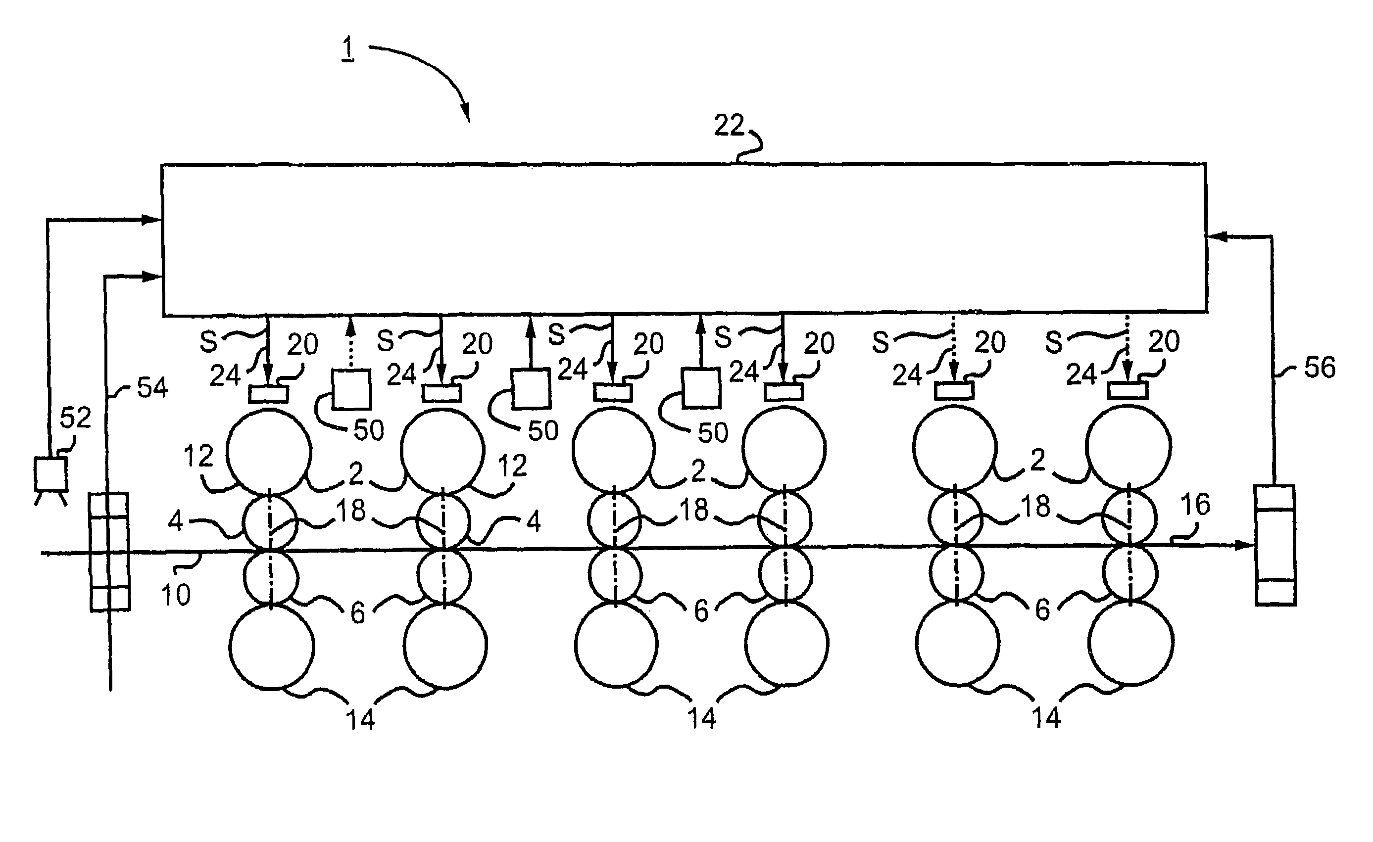
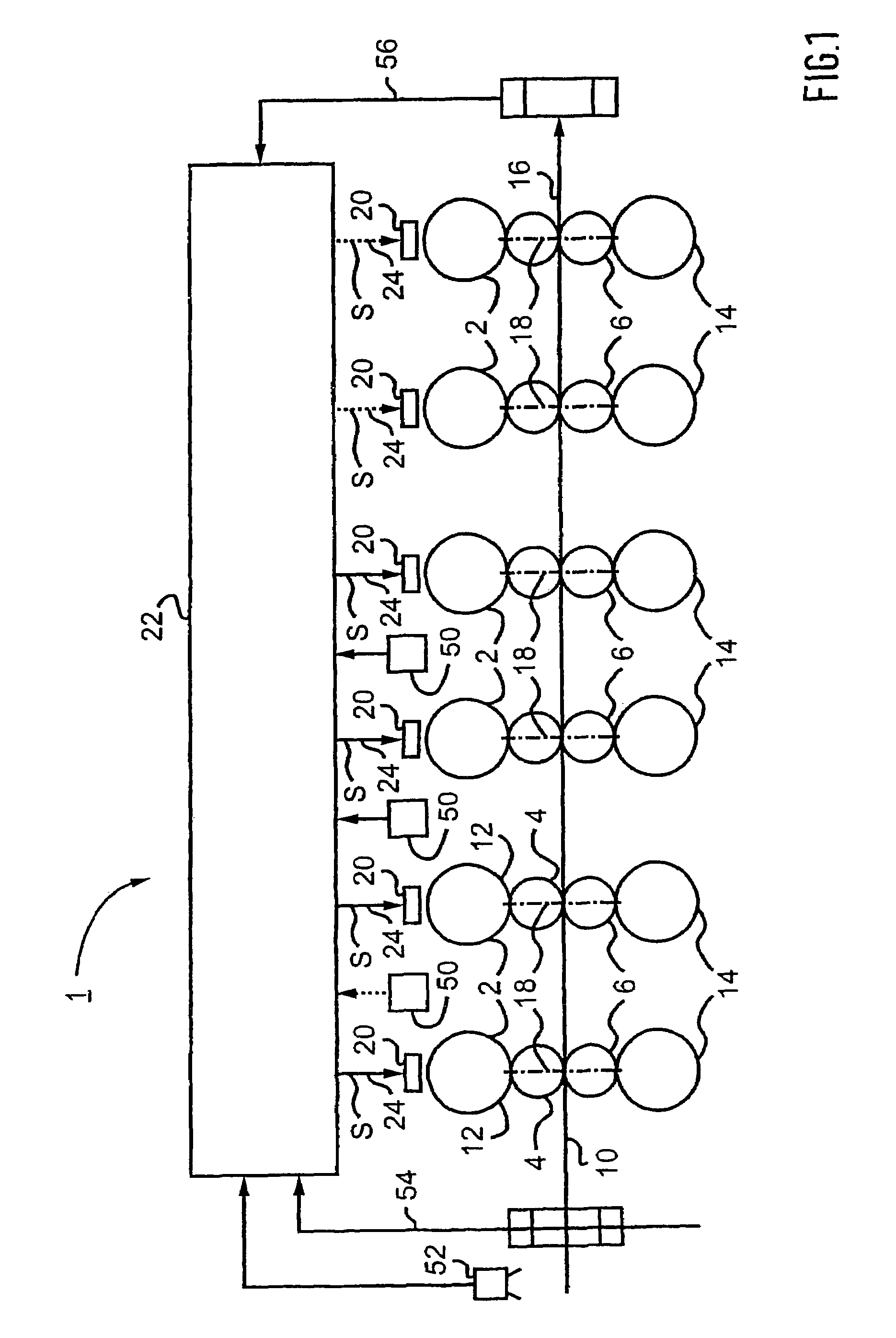
[0011]Advantageously, a control value for the swivel angle of one or each roll stand is preset as a function of the contour of the strip trailing end of the product that has already been rolled. Specifically, a suitable swivel value of the roll stand about its particular axis of rotation makes it possible to have an especially systemic effect on the strip flow.
[0013]Alternatively or additionally, the information obtained by the evaluation of the contour of the strip trailing end is advantageously used in the operation of a so-called looper. At constant tensile force, locally higher tensile stress can develop, e.g., in the case of narrowing width of the rolling stock in the region of its trailing end, and this can have the undesired consequence of the strip breaking. When the minimum width actually present is known on the basis of the evaluation of the contour of the strip trailing end, the tensile force acting on the particular looper can be appropriately reduced, as necessary, so that this type of break can be prevented. On the other hand, to avoid long strip slivers at the trailing end of the strip, a separate adjusting unit can be assigned to the edger, by which, for example, long strip slivers can be compensated by greater width reductions at the trailing end of the strip.
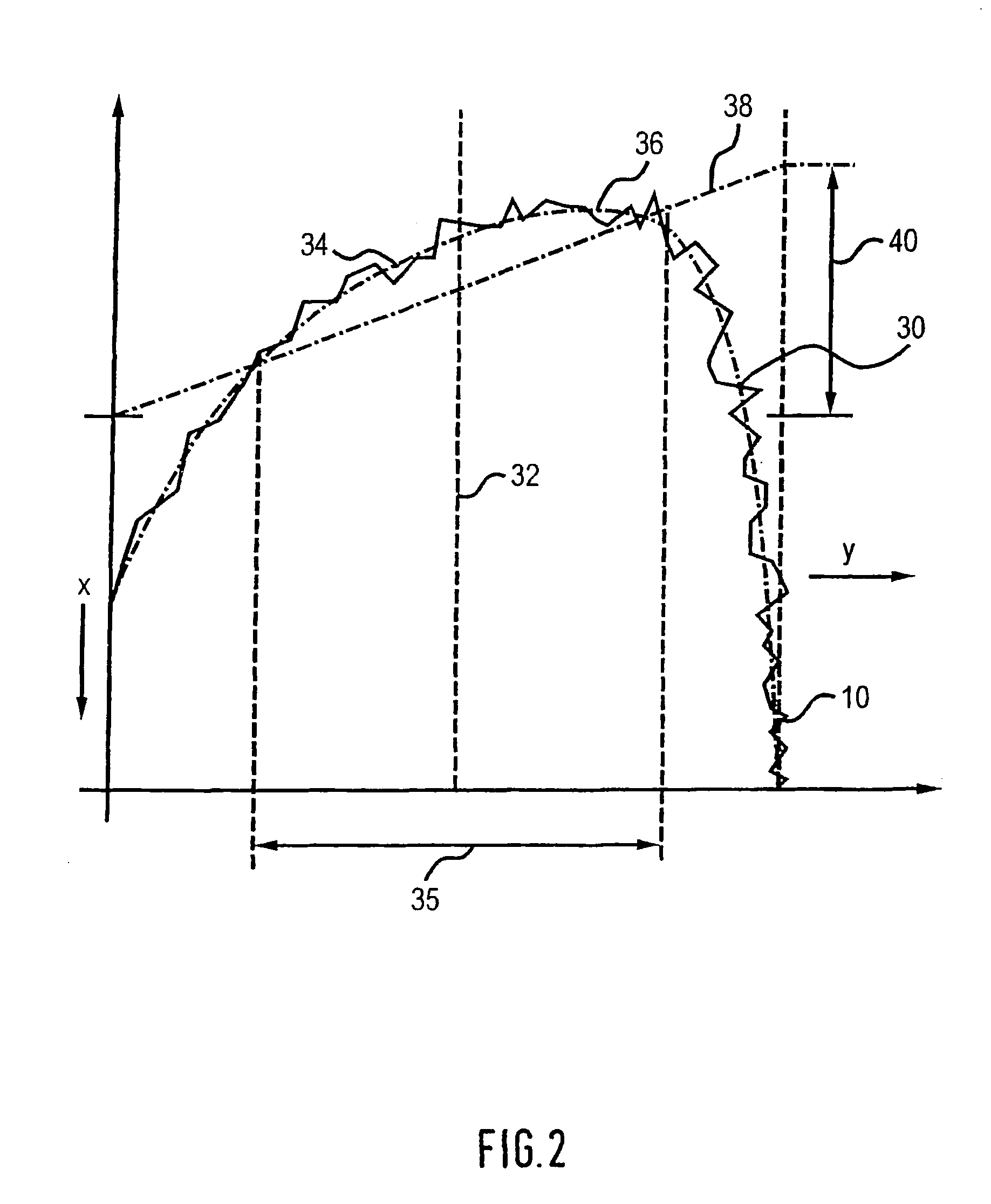
[0022]In order to keep the asymmetric tensile stresses in the roll stand as small as possible during its processing, the control value or each control value for the swivel angle of the given roll stand is advantageously readjusted in such a way that a contour of the strip trailing end develops which is symmetric with respect to the longitudinal center axis of the rolling stock. In this regard, minimization of a deviation of the contour of the strip trailing end from an asymmetric contour by suitable presetting of the control values for the swivel angle of the roll stands can be provided as a design criterion for an automatic control device assigned to the mill train.
[0024]In an especially advantageous refinement, especially great flexibility in the processing of the rolling stock can be achieved by presetting the set point for the position of the maximum in the width direction or the set point for the thickness taper of the strip trailing end in the extended plane as a function of the position of the given roll stand in the mill train. For example, strip-like rolling stock that is already asymmetrically formed in the strip cross-sectional direction can be worked in an especially advantageous way by first adjusting the swivel angle in the front roll stand as viewed in the rolling direction in such a way that the thickness taper of the entering strip-like rolling stock is restored, and the rolling stock is thus brought into a cross-sectional shape that is symmetric with respect to its longitudinal center axis. Of course, this makes it necessary to accept the development of strip lengthening of the rolling stock that is not uniform in the width direction in the front roll stand due to the variable material flow. However, due to the still relatively great thickness of the rolling stock in the front roll stand, this type of nonuniform strip lengthening is possibly tolerable. In the following roll stands as viewed in the rolling direction, a symmetric contour of the strip trailing end in the extended plane can be adjusted. This type of flexible presetting of the set points or reference input values for the automatic control thus allows reliable processing of rolling stock that is initially relatively unsymmetric into a relatively symmetric final rolled product with especially small strip flow errors. Different set points are also provided for the strip leading end, the strip middle section, and the strip trailing end.
[0027]To provide a reliable supply of suitable input parameters for the automatic control unit, it is advantageous for the automatic control unit to be connected on the input side with a number of measuring devices assigned to each roll stand for determining the contour in the extended plane of the strip trailing end and / or the strip leading end of the product that has already been rolled. The measuring devices can be installed, for example, on their assigned roll stand in an elevated position, so that it is possible to determine the contour of the strip trailing end in a top view of the rolling stock.
[0030]The advantages achieved with the invention consist especially in the fact that, by considering the contour of the strip trailing end of a previously rolled product in its extended plane in presetting the control values for the swivel angles of the roll stands, incorrect adjustments in the swiveling of the roll stands, which have an adverse effect on the rolling process and the rolling result, can be compensated in an especially simple and reliable way. In this regard, the detection of the incorrect adjustments by evaluation of preceding rolling results is provided in the manner of a learning or adaptive system, such that the contour of the strip trailing end, as a direct effect of the material flow in the strip-like rolling stock, allows an especially precise and reliable conclusion to be drawn about possible incorrect settings in the swivel angles of the roll stands. Moreover, the presetting of reference input values for the adjustment of the swivel angles as a function of the position of the given roll stand in the mill train allows especially flexible working of the rolling stock, so that even different types of preformed rolling stock can be worked with reliably high rolling quality.

Problems solved by technology

However, during working that is asymmetric with respect to the longitudinal central axis of the strip, the strip tension can also develop eccentrically.
Moreover, in the case of forces acting eccentrically on the rolling stock due to the strip tension, behavior of the strip trailing end that differs from that of the actual rolling stock can develop, which in turn can lead to rolling defects.
However, possible interventions with respect to achieving an especially good rolling result are limited, since, especially in the front roll stands as viewed in the rolling direction, necessary corrective measures are difficult to determine due to the still comparatively thick rolling stock present there, and since, in addition, the intervals between adjacent roll stands as viewed in the rolling direction are also comparatively difficult to inspect.

Method used


Image

  • Method for operating a mill train and a correspondingly embodied mill train
  • Method for operating a mill train and a correspondingly embodied mill train
  • Method for operating a mill train and a correspondingly embodied mill train

Examples


Embodiment Construction

[0035]The mill train 1 comprises a number of roll stands 2, each of which is designed as a multiple roll stand in the embodiment shown here. To this end, each roll stand 2 comprises a first work roll 4 and a second work roll 6, which together form a roll gap 8 and are designed for rolling stock 10 to pass between them. Each of the work rolls 4, 6 is reinforced by an associated backup roll 12, 14 on its side facing away from the rolling stock 10. The backup rolls in turn are contained in a housing, the details of which are not shown.

[0036]The mill train 1 is designed for the working of rolling stock that extends in an extended plane in the form of a strip. The strip-like rolling stock 10 has an essentially two-dimensional shape. Precisely for the working of this type of strip-like rolling stock 10, the so-called strip flow, i.e., the passage of the rolling stock 10 through the roll stands 2, is especially important. Accordingly, the mill train 1 is designed in such a way that the str...


PUM

PropertyMeasurementUnit
Temperatureaaaaaaaaaa
Thicknessaaaaaaaaaa
Angleaaaaaaaaaa

Abstract

The invention relates to a mill train (1) for milling a strip-type product to be milled (10). Said mill train comprises a number of roll stands (2) which are successively arranged in a milling direction (x) and which can be respectively pivoted about a rotational axis (18) which is essentially perpendicular to the milling direction (x). The aim of the invention is to maintain a belt run which favors a pre-determined milling result, in an especially simple and reliable manner. According to the invention, a control value (S) is pre-determined for the pivoting angle of a roll stand, or of each roll stand (2), according to the determined contour of the strip end (30) of a product (10) which has already been milled. According to the invention, additional control elements can also be used.

Description

[0001]This application is a national phase application of international application PCT / EP02 / 02131, filed Feb. 28, 2002.BACKGROUND OF THE INVENTION[0002]1. Field of the Invention[0003]The invention concerns a method of operating a mill train for rolling strip-like rolling stock with an edger and a number of roll stands arranged one behind the other in a rolling direction, each of which has an adjusting unit for affecting the contour of the strip trailing end of rolling stock. The invention also concerns a mill train of this type, which, in particular, is also provided with an edger at the run-in end for width reduction of the rolling stock.[0004]2. Description of the Related Art[0005]A number of roll stands can be used in a mill train for rolling a rolling stock. The roll stands, which are usually designed as so-called multiple roll stands and comprise a number of work rolls and, if necessary, a number of backup rolls, are provided for passing through a usually very elongated rollin...

Claims


Application Information

Patent Timeline
IPC IPC(8): B21B37/68B21B1/26B21B13/02B21B37/00B21B37/22B21B37/28B21B37/72
CPCB21B37/72B21B37/68B21B13/023B21B37/22B21B2263/20
Inventor SEIDEL, JURGEN
Owner SMS DEMAG AG
Learn More