Arrangement of a shaft with a mechanical face seal mounted thereon

Inactive Publication Date: 2011-03-22
EAGLEBURGMANN GERMANY GMBH &CO KG
View PDF11 Cites 0 Cited by
  • Summary
  • Abstract
  • Description
  • Claims
  • Application Information

AI Technical Summary

Benefits of technology

[0007]By virtue of the measures in accordance with the invention, the effect is achieved that, in operation of the mechanical face seal, a sufficiently strong current of a liquid medium which may be the medium requiring sealing (e.g. compressor oil) is fed along the seal gap which is defined between the seal faces of the cooperating seal rings in order to carry away any gas bubbles that have collected there, possibly from the medium requiring sealing, so as to thereby ensure that there is always a liquid medium at the seal gap. Gas bubbles when having entered the seal gap can cause dry-running of the mechanical face seal and thus excessive wear because of inadequate lubrication of the seal faces. At the same time, the flow medium can effectively cool the rotary seal ring and thus protect the arrangement from damage due to overheating. In order to increase the effect produced by the flow, provision may be made for the driver housing to comprise an element for diverting the stream of the flow medium towards the seal gap. In accordance with another particularly advantageous embodiment of the invention, the medium can be forced to flow along the rotary seal ring and the seal gap without the need for an externally

Problems solved by technology

Gas bubbles when having entered the seal gap can cause dry-running of the mechanical face seal and thus excessive wear because of inadequate lubrication of the seal faces.
These gas bubbles can settle out from the medium requiring sealing in th

Method used


Image

  • Arrangement of a shaft with a mechanical face seal mounted thereon
  • Arrangement of a shaft with a mechanical face seal mounted thereon

Examples


Embodiment Construction

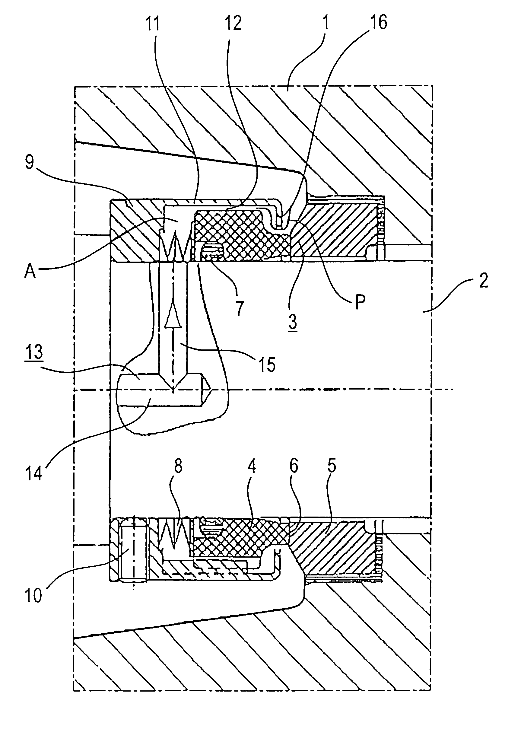
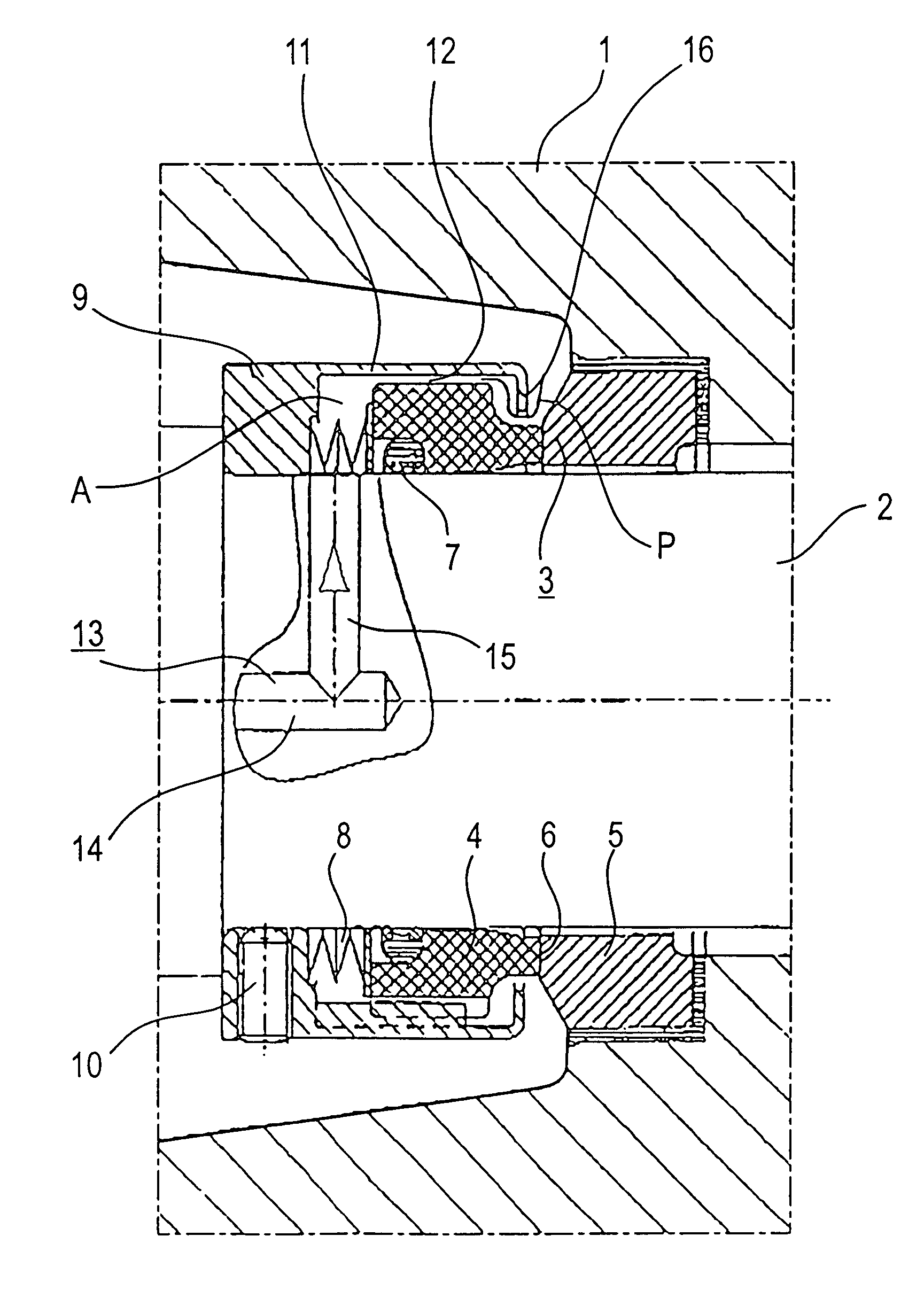
[0010]In the drawing, the reference symbol 1 relates to the housing of an apparatus requiring sealing, e.g. the housing of an air conditioning compressor, and the reference symbol 2 relates to a shaft, e.g. the drive shaft of the air conditioning compressor, which is passed through a boring in the housing. The reference symbol 3 relates to a mechanical face seal for sealing the interior of the housing at a portion where the shaft 2 passes through the boring in the housing.

[0011]Basically, the mechanical face seal 3 can be of conventional design and hence comprises a pair of cooperating seal rings 4, 5 having opposed seal faces in radial or essentially radial planes which define between each other and axially and radially delimit a seal gap 6 when in operation. One of the seal rings, the seal ring 5, is held in non-rotational manner on the housing 1 in a suitable but not particularly depicted manner and is sealed with respect to the housing 1.

[0012]The other seal ring 4 is provided f...


PUM


Abstract

An arrangement of a shaft with a slip-ring seal mounted thereon is disclosed. The slip-ring seal (3) comprises a pair of cooperating slip rings (4,5), the sealing faces of which define a sealing gap (6) between them. One of the slip rings is mounted on the shaft (2) with torque transmission from a drive element (9) mounted on the shaft, whilst the other slip ring is provided for fixed mounting on a stationary component. The arrangement is characterised in that the drive element (9) comprises a tubular drive housing (11), extending over the external circumference of the slip ring (4) with a radial gap (12) and a passage (13) for introduction of a flow medium is provided, opening out at one end in a chamber (A), defined by the drive housing (11), which drains out through the radial gap (12), whereby the radial gap forms a flow path for the flow medium which terminates at or near the sealing gap (6).

Description

BACKGROUND OF THE INVENTION[0001]1. Field of the Invention[0002]The invention relates to an arrangement of a shaft with a mechanical face seal mounted thereon. It relates, in particular, to an arrangement of a type mentioned in the preamble of the main claim which is especially suitable for sealing refrigerant compressors in motor vehicle air conditioning systems.[0003]2. Description of Related Art[0004]Mechanical face seals are known (Burgmann, ABC der Gleitringdichtung, self published 1988, page 156), wherein a torque is transmitted to the rotary seal ring through a driver device which is mounted on the shaft for rotation in common therewith. Furthermore, it is known (Burgmann, as above, page 236) to let a buffer fluid from an external source circulate through a chamber which is separated from the external environment and surrounds the seal gap of a mechanical face seal.SUMMARY OF THE INVENTION[0005]The object of the invention is to produce an arrangement of the type in question, ...

Claims


Application Information

Patent Timeline
IPC IPC(8): F16J15/34F04C27/00
CPCF04C27/009F16J15/3404
Inventor FEIGL, PETERLEDERER, ANDREASSIMON, CLEMENS
Owner EAGLEBURGMANN GERMANY GMBH &CO KG
Why Eureka
Try Eureka