Vapor chamber for cooling an electronic component

a technology for electronic components and vapor chambers, which is applied in the direction of reinforcement means, spacing means, lighting and heating apparatus, etc., can solve the problems of limited heat sinks, advanced cooling concepts, and high heat loss density, so as to improve the working liquid flow to the evaporator, reduce the stability of the pillars, and improve the effect of working liquid flow

Pending Publication Date: 2021-04-01
ABB (SCHWEIZ) AG
View PDF0 Cites 1 Cited by
  • Summary
  • Abstract
  • Description
  • Claims
  • Application Information

AI Technical Summary

Benefits of technology

[0043]It may be especially preferred that the at least one groove has at least one of a depth and a width in the range of 5 μm to 500 μm. It was found that especially grooves which are designed with such a size allow the effect of improving the working liquid to flow down to the evaporator is improved in an especially effective manner.
[0044]It may further be preferred that the that the smallest extension of an intermediate cross section area is smaller compared to the extension of both of the first contact area and the second contact area in a ratio of 1 to 100, such as 1 to 50, for example 1 to 10, such as 1 to 2. It was surprisingly found that especially such an arrangement allows a high stability, so that the above-described advantages are reached in an especially effective manner, thereby not negatively influencing the working behaviour and thus the cooling behaviour of the vapor chamber.
[0045]The same may be applied in case the smallest intermediate cross section area has an extension in a range of 0.03 to 1950 mm2, preferably of 0.2 to 300 mm2. Even though the above described effect may be reached reliably, the thickness of the pillars is large enough in order not to reduce the stability of the pillars as such in a too significant manner. Thus, the thickness of the pillars does not counteract to the achieved improvement in mechanical stability.

Problems solved by technology

This leads to higher heat loss densities which require advanced cooling concepts.
In fact, traditional Aluminum or Copper heat sinks are limited by heat flux densities of 10 W / cm2.

Method used


Image

  • Vapor chamber for cooling an electronic component
  • Vapor chamber for cooling an electronic component
  • Vapor chamber for cooling an electronic component

Examples


Embodiment Construction

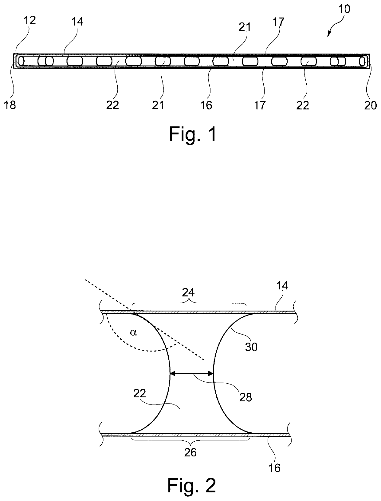
[0062]FIG. 1 shows a vapor chamber 10 which is particularly suited for cooling an electronic device, such as a power semiconductor module, not shown as such.

[0063]The vapor chamber 10 comprises casing 12 which is sealed to the outside so that a working fluid which is included in the casing 12 is not able to leave the casing 12 either in liquid or in gaseous form. The casing 12 comprises two main walls. The two main walls comprise an evaporator wall 14 and a condenser wall 16. The evaporator wall 14 is configured for coming in contact with a device to be cooled, such as with a baseplate of a power semiconductor module. The condenser wall 16 is configured for being in an environment having a comparably cooler temperature. For example, the condenser wall 16 is provided at its outside with air fins.

[0064]The two main walls, i.e. the evaporator wall 14 and the condenser wall 16, are connected by side connections 18, 20 to form a sealed volume 21 inside the two main walls and the side con...


PUM


Abstract

The invention relates to a vapor chamber (10), comprising a sealed casing (12) which comprises two main walls, wherein a first main wall is an evaporator wall (14) and a second main wall is a condenser wall (16), wherein the two main walls are connected by side connections (18, 20) to form a sealed volume (21) inside the two main walls and the side connections (18, 20), wherein a plurality of pillars (22) is provided in the sealed volume (21) such, that the pillars (22) connect the evaporator wall (14) and the condenser wall (16), wherein the pillars (22) have a first contact area (24) to the evaporator wall (14) and a second contact area (26) to the condenser wall (16), and wherein the pillars (22) further comprise an intermediate cross section area (28) being arranged between the first contact area (24) and the second contact area (26), wherein the extension of the intermediate cross section area (28) is smaller compared to the extension of both of the first contact area (24) and the second contact area (26).

Description

TECHNICAL FIELD[0001]The invention relates to a vapor chamber for cooling an electronic component, such as for cooling a power semiconductor device. The present invention particularly relates to a cooling chamber having an improved mechanical stability and is further easy to produce.BACKGROUND ART[0002]Vapor chambers are known in the art. Such vapor chambers are used for dissipating heat such as from electronic parts. Additionally to two-dimensional vapor chambers, so-called three-dimensional vapor chambers are known which comprise an evaporator and at least a condenser being provided in a T-like arrangement.[0003]The current ratings of power electronic devices are continuously increasing while maintaining or even reducing their footprint. This leads to higher heat loss densities which require advanced cooling concepts. In fact, traditional Aluminum or Copper heat sinks are limited by heat flux densities of 10 W / cm2. Recently vapor chamber heat sinks which are state of the art techn...

Claims


Application Information

Patent Timeline
Patent Type & Authority Applications(United States)
IPC IPC(8): F28F3/12F28D15/02
CPCF28F3/12F28F2225/04F28D15/0233H05K7/20336H01L23/427F28D15/046F28F2225/02F28F2240/00
Inventor BORTOLATO, MATTEOAGOSTINI, BRUNOPETROV, ANDREYTORRESIN, DANIELE
Owner ABB (SCHWEIZ) AG
Why Eureka
Try Eureka