Automated ultrasonic cleaning apparatus with trigger means for draining fluid therefrom

a technology of ultrasonic cleaning and trigger means, which is applied in the direction of cleaning using liquids, valve details, valve arrangements, etc., can solve the problems of affecting the use of the equipment, consuming valuable space in the laboratory or medical environment, and increasing the risk of cross-contamination, so as to improve the efficiency of the ultrasonic cleaning equipment and facilitate the production, maintenance and operation. , the effect of automating the execution of the ultrasonic cleaning operation

Active Publication Date: 2011-07-26
KLENZ ULTRASONICS LLC
View PDF13 Cites 0 Cited by
  • Summary
  • Abstract
  • Description
  • Claims
  • Application Information

AI Technical Summary

Benefits of technology

[0009]It is an advantage of the present invention to provide an improved ultrasonic cleaner for surgical, medical, dental and laboratory instruments.
[0010]It is another advantage of the present invention to provide an improved ultrasonic cleaner that is easily manufactured, maintained and operated within the space constraints of a medical and / or laboratory facility.
[0011]It is a further advantage of the present invention to provide an improved ultrasonic cleaner that employs a trigger mechanism to selectively drain fluid from a retention tank and thereby execute cleaning, rinsing, drying and optioning pre-soaking processes in a single tank.
[0012]In accordance with these and other advantages, the present invention provides an apparatus for automated execution of an ultrasonic cleaning operation in an aqueous solution. The present invention ultrasonic cleaner includes a tank with a valve means in fluid communication therewith for supply of water thereto during the cleaning operation. A bottom tank portion is provided with an external surface and an internal surface defining a predetermined thickness therebetween. At least one drainage aperture is provided in the bottom portion that facilitates egress of the solution from the tank after cleaning and rinsing modes of the ultrasonic cleaning operation. At least one wall depends from the bottom tank portion so that a retention region for said solution is defined thereby. At least one ultrasonic transducer is removably secured to at least one of the bottom tank portion and the tank wall to induce cavitation in the solution. A partition having at least one aperture defined therethrough is provided in the retention region to define at least one service section and at least one support section thereby.
[0013]A trigger means is operatively disposed in the support section to effect unimpeded flow of the solution through the drainage aperture during the ultrasonic cleaning operation. The trigger means comprises a drainage flapper in operable communication with a signal means (such as a solenoid) between a first rest position, in which the flapper impedes flow of the solution through the drainage aperture, and a second elevated position, in which the flapper is elevated relative to the drainage aperture to facilitate unimpeded fluid flow therethrough. The trigger means further comprises a connecting means in operable communication with the drainage flapper and the signal means, which connecting means may be an articulatable arm that is responsive to the signal means to move the drainage flapper between its first rest and second elevated positions during the ultrasonic cleaning operation. The signal means is in electrical communication with a liquid level sensor disposed in either of the service section or the support section, which sensor detects the level of the solution in the tank and indicates such level to the signal means to operate the drainage flapper accordingly. A programmable controller may also be provided for programmable timing and sequence of drainage flapper operation.
[0014]A portion of the tank wall that is provided in the support section of the tank includes a fluid intake aperture that establishes fluid communication between the valve means and the tank and an overflow aperture that accommodates inadvertent overflow of the solution from the tank during the ultrasonic cleaning operation. A conveyance conduit is selectively disposed in communication with the overflow aperture to accommodate egress of overflow from the tank to a sewer disposal or receptacle.

Problems solved by technology

The need to transfer medical instruments among the tanks (either manually or automatically), however, substantially elevates the risk of cross-contamination due to re-use of solutions or inattention to identification of instruments.
Even in these improved models, a hot air drying means is disposed in a tank cover, thereby creating a heavy device that consumes valuable space in a laboratory or medical environment and inhibits use due to the enhanced effort required to lift the tank cover for proper cleaner operation.
Although the cleaner disclosed by Kotsopey effectively integrates cleaning, rinsing and drying functions in an automated operation, the cleaner integrates additional structure such as overflow weirs and perforated air distribution channels that provide a heavy, cumbersome structure that is expensive to manufacture and maintain.
Although the aforementioned cleaners sufficiently sanitize medical instruments from immersion processes executed therein, such devices are cumbersome for laboratory and medical applications.
The tank constructions of such devices require extra structure that contributes to tank weight and maintenance.
For instance, a separate compartment that is required for drying the instruments contributes to manufacturing and maintenance costs and deleteriously exposes electrical components to excess solution.
In medical and laboratory environments, such conditions are detrimental to consideration of space constraints and further inhibit proper use of such cleaning devices, thereby contributing to cross contamination risks.

Method used


Image

  • Automated ultrasonic cleaning apparatus with trigger means for draining fluid therefrom
  • Automated ultrasonic cleaning apparatus with trigger means for draining fluid therefrom
  • Automated ultrasonic cleaning apparatus with trigger means for draining fluid therefrom

Examples


Embodiment Construction

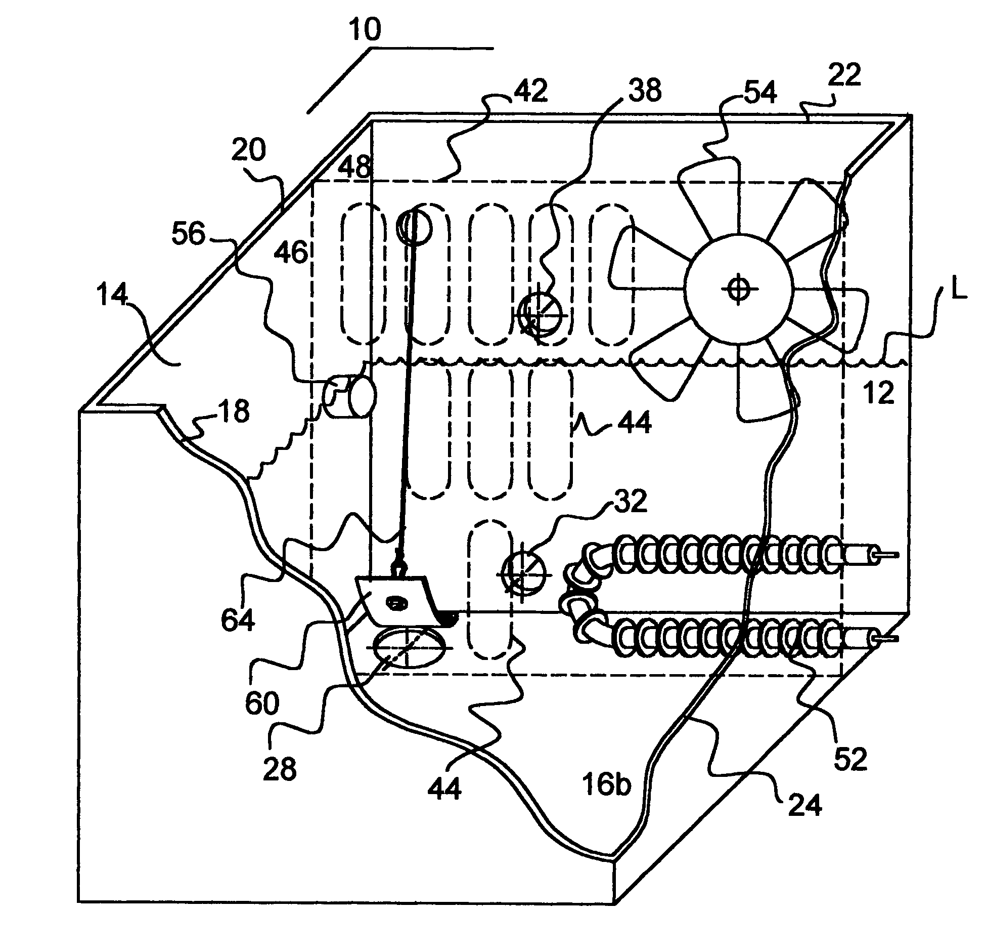
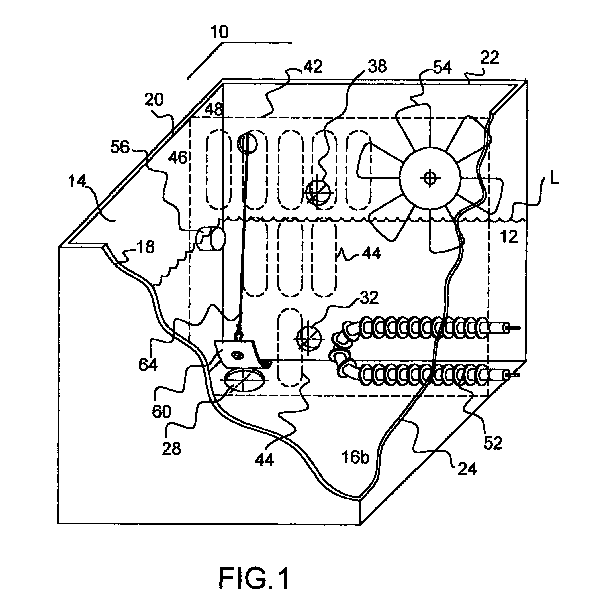
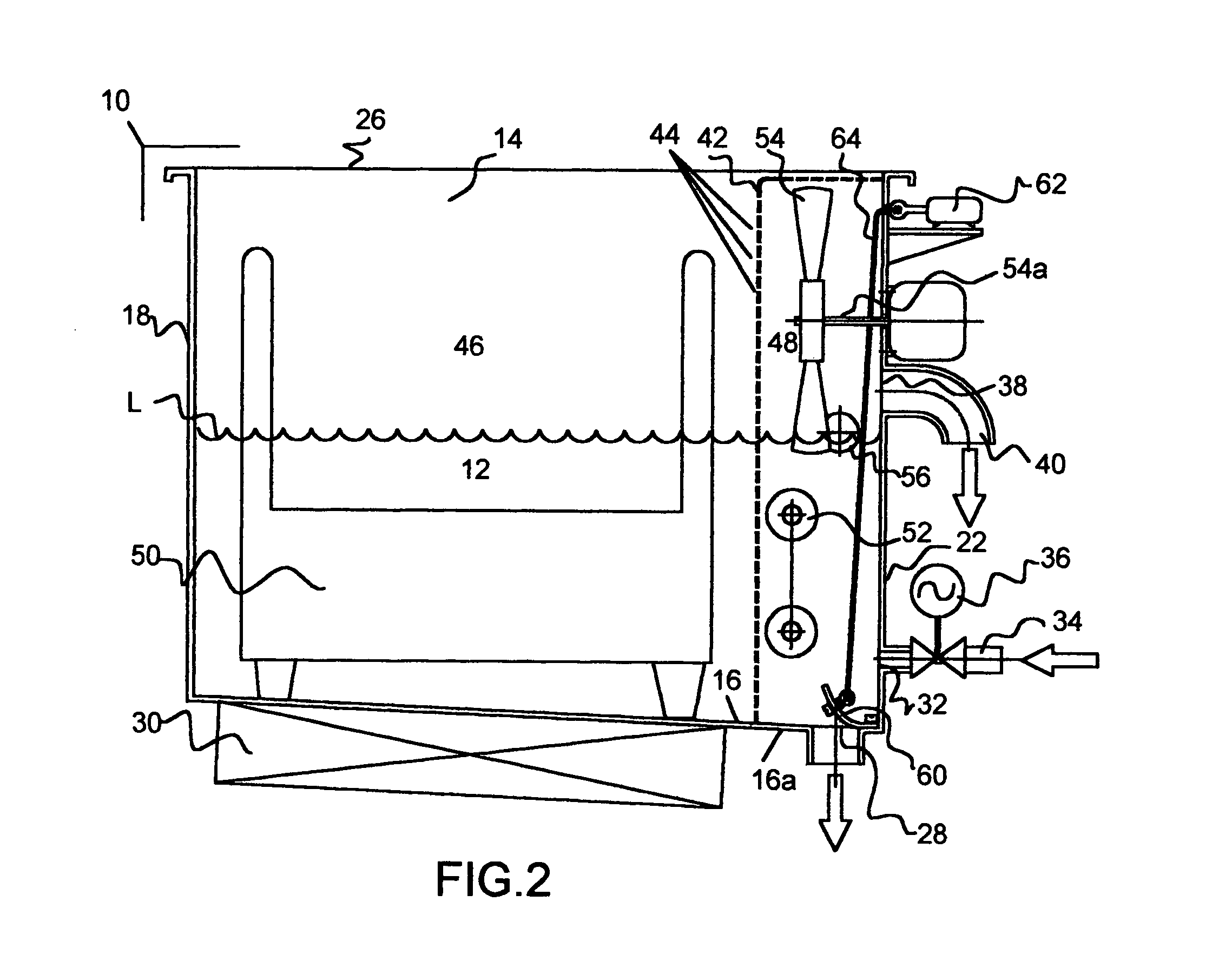
[0019]Now referring to the figures, wherein like numbers identify like elements, an automated ultrasonic cleaning apparatus 10 of the present invention is provided in FIGS. 1 and 2. Cleaning apparatus 10 executes a complete ultrasonic cleaning operation, which herein comprises a cleaning mode, a rinsing mode and a drying mode (as further described hereinbelow). In typical aqueous ultrasonic cleaning systems, contaminants are removed during the cleaning mode. The rinse stage removes any effluents and residual detergent, and a dryer removes any remaining rinse water. An optional pre-soaking mode may also be performed prior to the cleaning mode to inhibit adhesion of bodily fluids and effluents to the instruments to be cleaned.

[0020]Fluid 12 that is employed in the pre-soaking, cleaning and rinsing modes alternately comprises pure water that is delivered to apparatus 10 by a fluid conduit (as described further hereinbelow) and a solution that is employed in the cleaning mode. The solut...


PUM


Abstract

The present invention discloses an ultrasonic cleaner in which an automated ultrasonic cleaning operation is executed using an aqueous solution. The cleaner includes a tank having a valve means in fluid communication therewith, a bottom tank portion with at least one drainage aperture therethrough and at least one tank wall depending therefrom to provide a solution retention region. At least one ultrasonic transducer is removably secured to one of the tank bottom and tank wall. A partition in the solution retention region has at least one aperture defined therethrough and defines a service section and a support section thereby. A trigger means operatively disposed in the support section comprises a drainage flapper in operable communication with a signal means between a first rest position, in which the flapper impedes flow of the solution through the drainage aperture, and a second elevated position, in which the flapper is elevated relative to the drainage aperture to facilitate unimpeded fluid flow therethrough.

Description

FIELD OF THE INVENTION[0001]The present invention is directed to an improved ultrasonic cleaning apparatus for optimal sanitation of medical and dental instruments. The ultrasonic cleaning apparatus of the present invention employs a single tank having dual compartments to facilitate automatic completion of cleaning, rinsing and drying steps in an ultrasonic cleaning operation. A first compartment retains items to be cleaned therewithin apart from a second compartment that houses trigger means for drainage of fluid from the tank. In this configuration, the ultrasonic cleaner of the present invention eliminates costly automated elements without compromising beneficial sanitation of the instruments to be cleaned.BACKGROUND AND SUMMARY OF THE INVENTION[0002]Manufacturers and surface treaters from a variety of industries and professions have long recognized ultrasonic cleaning as an effective means of removing contaminants from a wide variety of substrates. The process has been embraced...

Claims


Application Information

Patent Timeline
Patent Type & Authority Patents(United States)
IPC IPC(8): B08B3/12
CPCB08B3/12F16K31/0655F16K31/465Y10S134/902
Inventor PROKOPENKO, ALEKSANDR
Owner KLENZ ULTRASONICS LLC
Why Eureka
Try Eureka