
Backlight module

a backlight module and backlight technology, applied in the field of display, to achieve the effect of improving the color purity and luminous intensity of green light, increasing the color gamut of the backlight module, and enhancing luminance intensity

Active Publication Date: 2018-07-19
WUHAN CHINA STAR OPTOELECTRONICS TECH CO LTD
View PDF12 Cites 0 Cited by
  • Summary
  • Abstract
  • Description
  • Claims
  • Application Information

AI Technical Summary

Benefits of technology

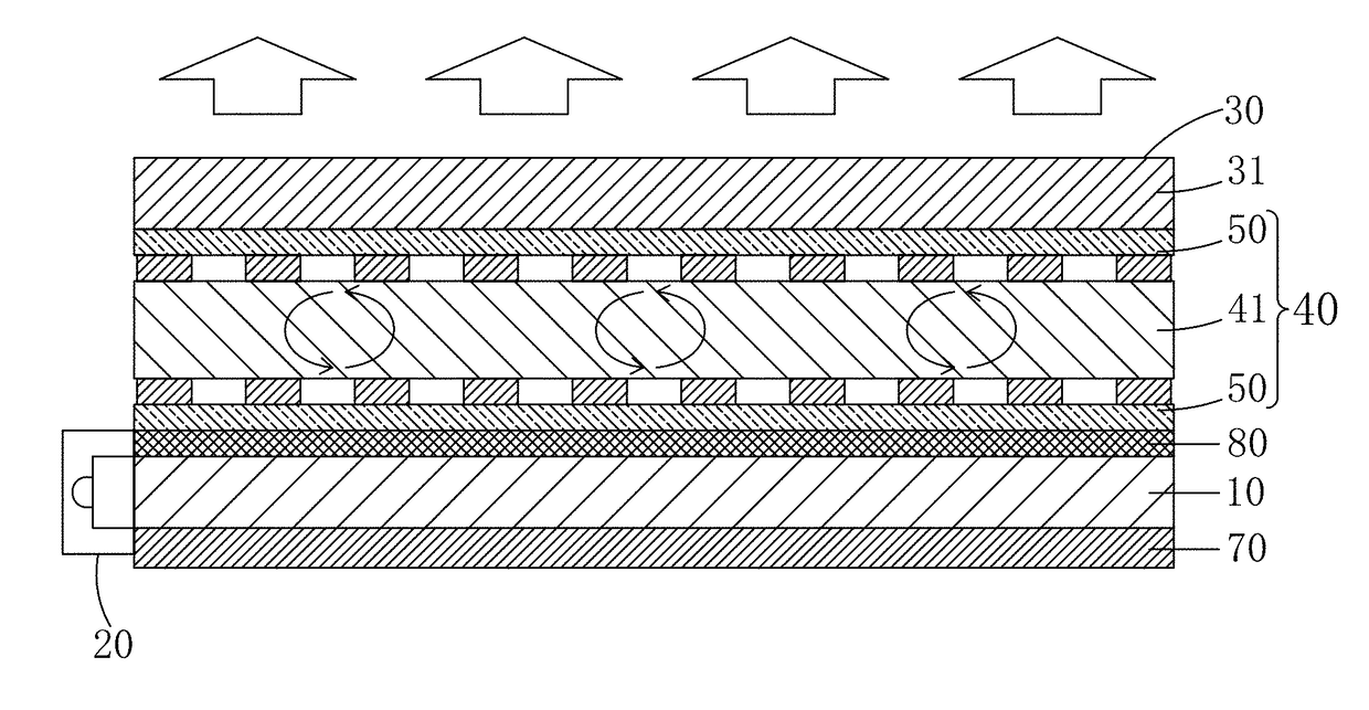
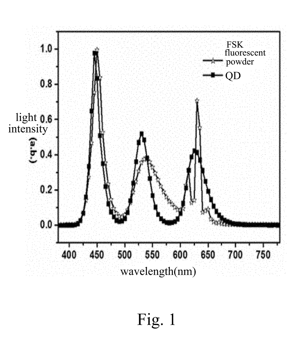
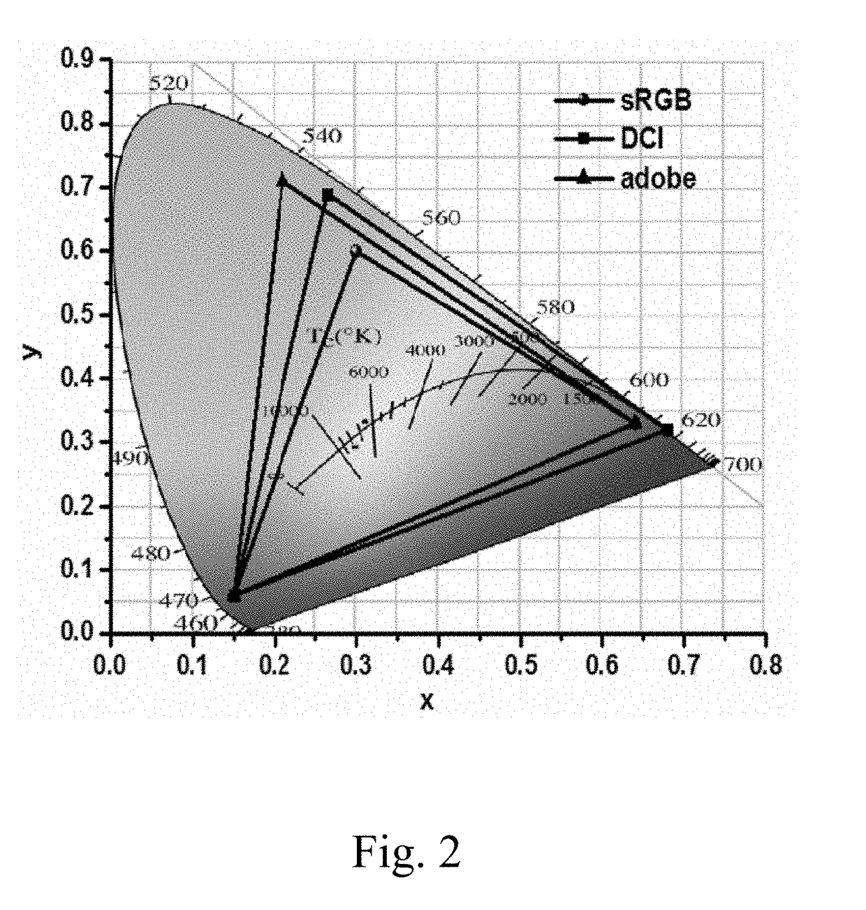
The present invention provides a backlight module that improves the color purity and luminance of green light to increase the gamut. It uses blue backlight to excite red and green QD films to obtain red and green fluorescence. Two metal wire grids are placed on both sides of the green QD film to form a Fabry-Perot cavity, which selectively enhances the luminance intensity of a specific wavelength of green light and improves color purity and luminous intensity of the green light, thus increasing the color gamut of the backlight module. The metal wire grid also improves the low efficiency problem of fluorescence QD film and forms a brightness enhancing structure with the reflective layer of the backlight module to save setting up a separate brightness enhancing structure and reduce the thickness of the backlight module.

Problems solved by technology

Moreover, the high gamut property of the organic light-emitting diode (OLED) technology places a challenge to the conventional LCD.

Method used


Image

  • Backlight module
  • Backlight module
  • Backlight module

Examples


Embodiment Construction

[0028]To further explain the technical means and effect of the present invention, the following refers to embodiments and drawings for detailed description.

[0029]Refer to FIG. 3. The present invention provides a backlight module, which comprises: a light-guiding plate 10, a blue light source 20 disposed on one side of the light-guiding plate 10, and a red light conversion layer 30 and a green light conversion layer 40 stacked and disposed above the light-exiting side of the light-guiding plate 10, wherein the red light conversion layer 30 being stacked on top of the green light conversion layer 40, or vice versa.

[0030]The red light conversion layer 30 comprises a red quantum dot (QD) film 31.

[0031]The green light conversion layer 40 comprises a green QD film 41, and two metal wire grids 50 disposed respectively on both sides of the green QD film 41.

[0032]The metal wire grid 50 comprises a dielectric layer 90 and a plurality of metal wire grid units 60 disposed on the dielectric laye...


PUM

PropertyMeasurementUnit
wavelengthaaaaaaaaaa
heightaaaaaaaaaa
widthaaaaaaaaaa

Abstract

The invention provides a backlight module, using blue backlight to excite the red, green QD films to obtain red and green fluorescence; and disposing two metal wire grids on both sides of the green QD film to form a Fabry-Perot cavity, the Fabry-Perot cavity able to select and enhance luminance intensity of a specific wavelength selected from the green light emitted by the green QD film so as to improve color purity and luminous intensity of the green light, and thus increase the color gamut of the backlight module, as well as improve the luminous efficiency of the green QD film, and significantly improve the low efficiency problem of fluorescence QD film. Moreover, the metal wire grid may form a brightness enhancing structure with the reflective layer of the backlight module to save setting up a brightness enhancing structure and reduce the thickness of the backlight module.

Description

BACKGROUND OF THE INVENTION1. Field of the Invention[0001]The present invention relates to the field of display, and in particular to a backlight module.2. The Related Arts[0002]In the rapid development of display technology, the liquid crystal display (LCD) has the advantages of thinness, high display quality, and low power consumption, and is widely used in applications, such as, mobile phone, TV, personal digital assistant (PDA), digital camera, notebook PC, desktop PC, and so on, to become the mainstream display technology.[0003]The majority of consumer LCDs is mostly backlight-type LCD, which comprises a liquid crystal (LC) display panel and a backlight module. The operation principle of the LCD is to dispose LC molecules between two parallel glass substrates, with a plurality of vertical and horizontal tiny wires between the two glass substrates. By allowing the electricity to flow through or not to change the orientation of LC molecules, the light emitted from the backlight i...

Claims


Application Information

Patent Timeline
Patent Type & Authority Applications(United States)
IPC IPC(8): G02F1/1335F21V8/00
CPCG02F1/133602G02B6/0031G02F1/133528G02F2001/133548G02F1/133615G02F1/133614G02B6/005G02B6/0056G02F1/13362G02F2202/108G02F1/1336G02F1/133548
Inventor ZHA, GUOWEI
Owner WUHAN CHINA STAR OPTOELECTRONICS TECH CO LTD
Learn More