
System and simulator for the disengageable simulation of installations or machines within programmable logic controllers

a technology of programmable logic controller and simulator, which is applied in the direction of electrical programme control, program control, instruments, etc., can solve the problems of additional costs, complex setup of simulation environment, and integration of controllers into the simulation environmen

Inactive Publication Date: 2018-07-19
SIEMENS AG
View PDF3 Cites 1 Cited by
  • Summary
  • Abstract
  • Description
  • Claims
  • Application Information

AI Technical Summary

Benefits of technology

The patent describes a system that allows for the simulation of machines and installations within programmable logic controllers. The system ensures that the control program and simulation program are separate and can communicate with each other without error. The simulation program can be executed between program cycles, and a virtual clock is stopped during the simulation to avoid errors. The use of multiple processor cores is also possible. The system is connected to the controller, meaning no additional test hardware is required, and it saves time during fast test mode or productive mode changes. The system allows for quick testing scenarios in case of a fault. Overall, this system improves the quality and efficiency of programmable logic controllers.

Problems solved by technology

Problems during the use of simulation environments are usually the following: the complexity for setting up a simulation environment is considerable for several reasons, since simulation systems require incorporation because they are programmed in other languages, and since integration of a controller into a simulation system is complex because the signals of the two systems need to be assigned individually and often “manually”.
Further, the simulation system is often available only during development, but not in the event of later changes or troubleshooting in the installation.
Finally, additional costs arise, since simulation systems require additional computer systems and software also costs money.
Secondly, modification of the control code for the purpose of simulation also entails a few problems: the installation of test logic requires the control code to be changed, which is an additional source of error and makes the control code less clear, i.e. it is no longer the original code that is tested, but rather an adapted code.
The test logic is not needed at all in productive mode, or it can be inadvertently activated or deactivation can be forgotten after initiation, which is a source of error, and in test mode the additional test logic corrupts the timing, since the additional code also needs to be executed, of course.
This is effected unsystematically, however, and is not 100% checkable by virtue of subsequent tests.

Method used


Image

  • System and simulator for the disengageable simulation of installations or machines within programmable logic controllers
  • System and simulator for the disengageable simulation of installations or machines within programmable logic controllers
  • System and simulator for the disengageable simulation of installations or machines within programmable logic controllers

Examples


Embodiment Construction

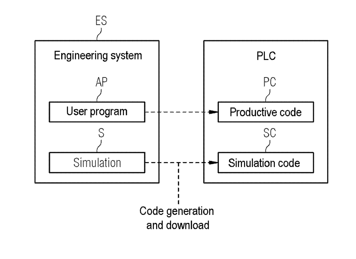
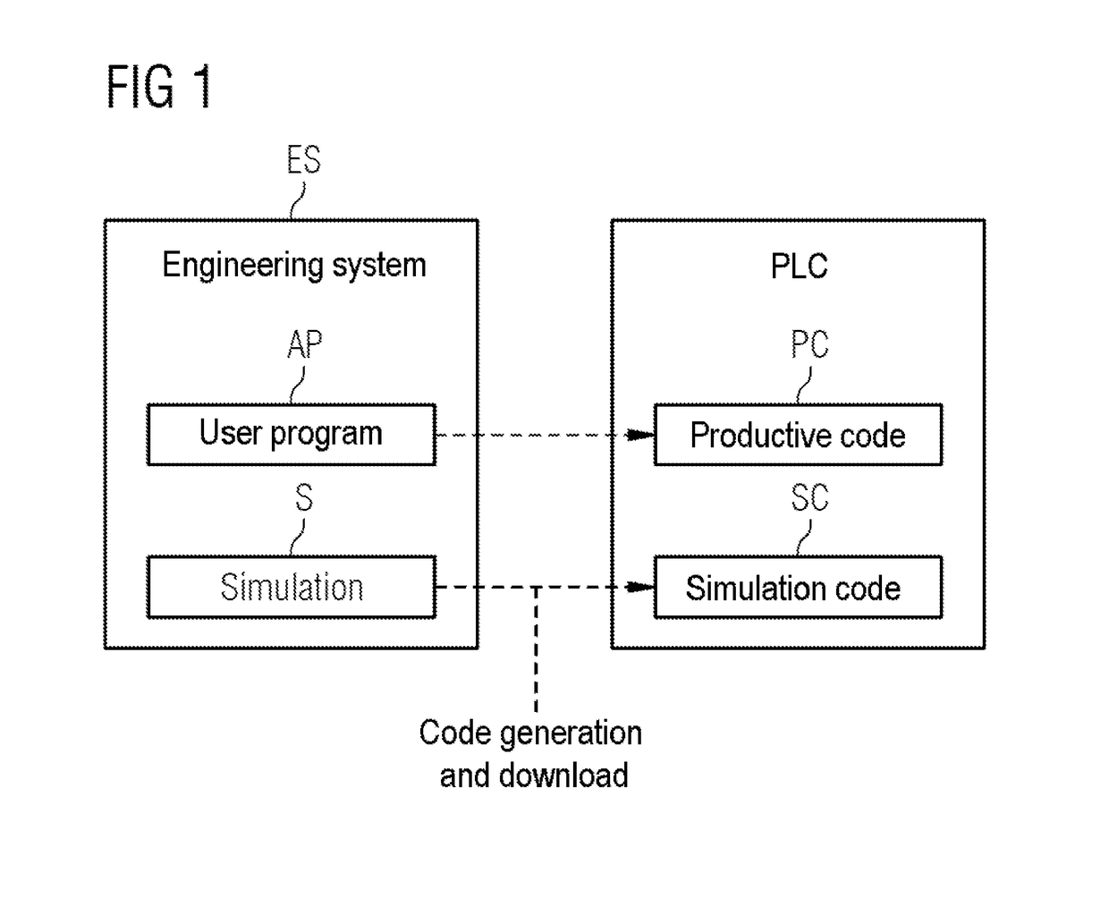
[0017]FIG. 1 shows an overview depiction to explain embodiments of the invention in terms of an engineering system ES and programmable logic controller PLC, wherein an application program AP that is present in the engineering system leads to a productive code PC in the programmable logic controller PLC and, separately therefrom, generates a code from a simulation program S in the engineering system ES and, as simulation code SC, is separately likewise loaded into the programmable logic controller PLC.

[0018]The simulation code SC is programmed using a PLC language and is executed by an IO simulator that is advantageously integrated in a programmable logic controller PLC.

[0019]The IO simulator is part of the controller, runs within the same context and can access the internal data memories within the control system.

[0020]To separate the responsibilities, the two parts “productive code” and “simulation code” are distinguished from one another. The PLC manages a simulation code exclusiv...


PUM


Abstract

Provided is a system and a simulator for the disengageable simulation of installations or machines within programmable logic controllers, in which control program and simulation program are strictly separate within the same processing environment, wherein the direction of access for the input / output memory area during normal operation and the consistent reversal thereof in the simulation part are ensured, and which involves the simulation program being executed between the program cycles, with a virtual clock being stopped during the simulation. As a result, the test on an unaltered user program in the PLC avoids errors in the startup or test phase through code changes, and a timing response as in the genuine installation, particularly in the event of tests on timers and under race conditions, achieves a higher level of program quality through better test results.

Description

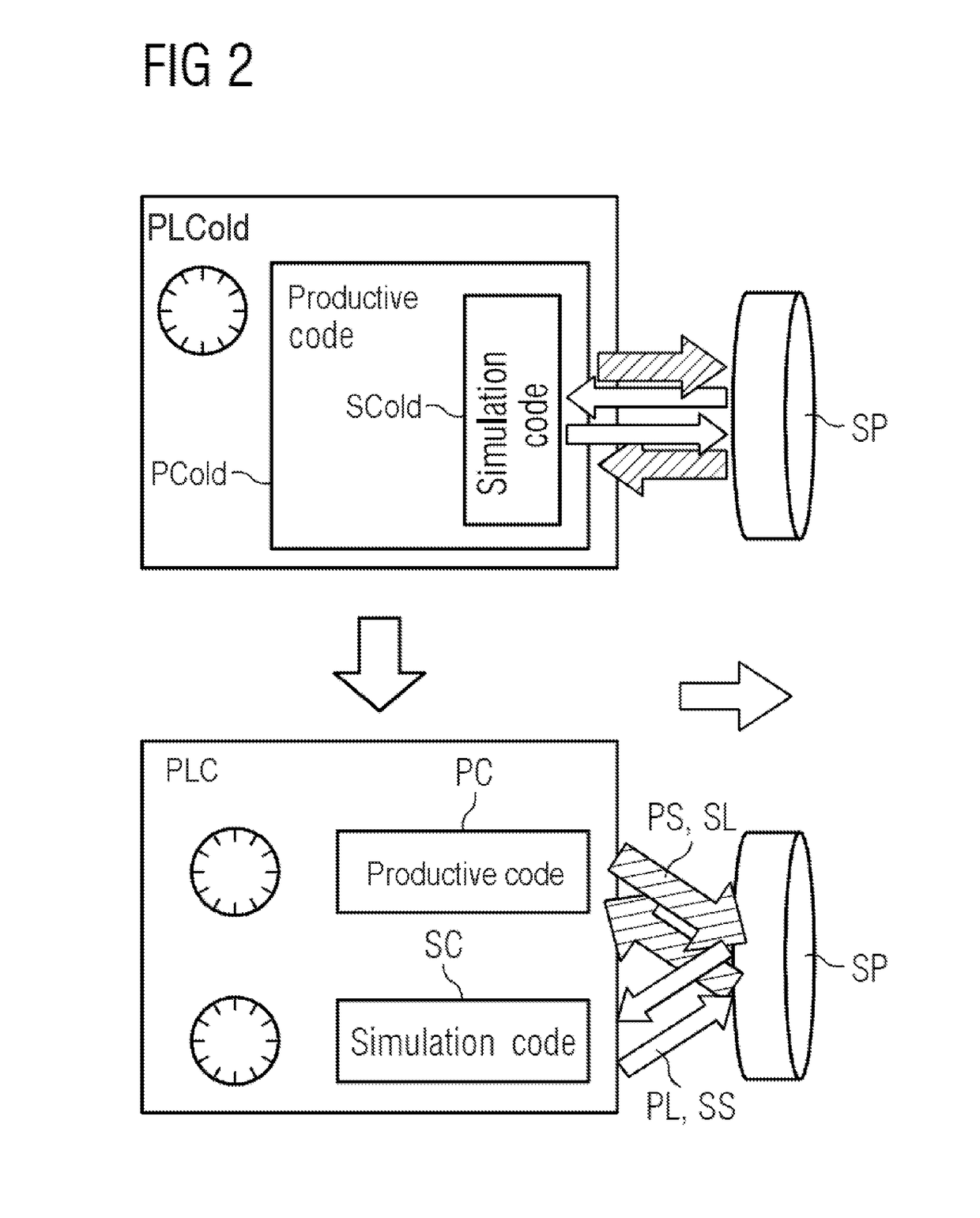
CROSS-REFERENCE TO RELATED APPLICATIONS[0001]This application claims priority to European application No. 17151591.9 having a filing date of Jan. 16, 2017, the entire contents of which are hereby incorporated by reference.FIELD OF TECHNOLOGY[0002]The following relates to a system and a simulator for the disengageable simulation of installations or machines within programmable logic controllers (PLCs) having an installation interface for a productive mode, which installation interface is present to output installation control data to the installation and to receive installation data from the installation, and having a further interface, separate from the installation interface, for a simulation mode.BACKGROUND[0003]In the surroundings of the programmable logic controllers (PLCs), program code is written that controls installations or machines. This code needs to be tested. In order to test realistically, however, the environment in which the controller will later operate needs to be ...

Claims


Application Information

Patent Timeline
Patent Type & Authority Applications(United States)
IPC IPC(8): G06F17/50G05B19/05
CPCG05B2219/13186G06F17/5086G05B19/05G06F11/25G06F11/261G05B19/054G05B2219/13185G06F30/17
Inventor ERMLER, RENEKREBS, CORNELIANEIDIG, JORGQUIROS ARAYA, GUSTAVO
Owner SIEMENS AG
Learn More