Method for manufacturing and device for manufacturing ultrafine fiber nonwoven fabric

a manufacturing method and nonwoven fabric technology, applied in the direction of filament/thread forming, spinnerette pack, melt spinning methods, etc., can solve the problems of large-sized apparatus drawback and no extension effect of fiber, and achieve the effect of enhancing the strength of ultrafine fiber

Inactive Publication Date: 2018-07-26
KASEN NOZURU SEISAKUSHO
View PDF1 Cites 1 Cited by
  • Summary
  • Abstract
  • Description
  • Claims
  • Application Information

AI Technical Summary

Benefits of technology

[0006]In order to solve the above problems, according to the present disclosure, it is not always necessary to include the slits in both sides of the nozzle hole. Accordingly, the reason why the conventional spinning die includes the slits in both sides of the nozzle hole is considered that the thermoplastic polymer is melt blown from the nozzle hole 2 by jetting hot air to the axis direction of the nozzle and the melt blown ultrafine fiber is extended to the direction of the axis to enhance the strength of the ultrafine fiber. However, it has been found that, even if hot air is jetted to the direction of axis of the ultrafine fiber in the condition, because the ultrafine fiber is floating in the air, almost no extension effects of the fiber are obtained.

Problems solved by technology

However, the spinning die 1 needs to have the pipes 6, 6, the hot air passages 5, 5 and the slits 4, 4 in both sides of the nozzle hole, to result in a drawback of a large-sized apparatus.
However, it has been found that, even if hot air is jetted to the direction of axis of the ultrafine fiber in the condition, because the ultrafine fiber is floating in the air, almost no extension effects of the fiber are obtained.

Method used


Image

  • Method for manufacturing and device for manufacturing ultrafine fiber nonwoven fabric
  • Method for manufacturing and device for manufacturing ultrafine fiber nonwoven fabric
  • Method for manufacturing and device for manufacturing ultrafine fiber nonwoven fabric

Examples


Embodiment Construction

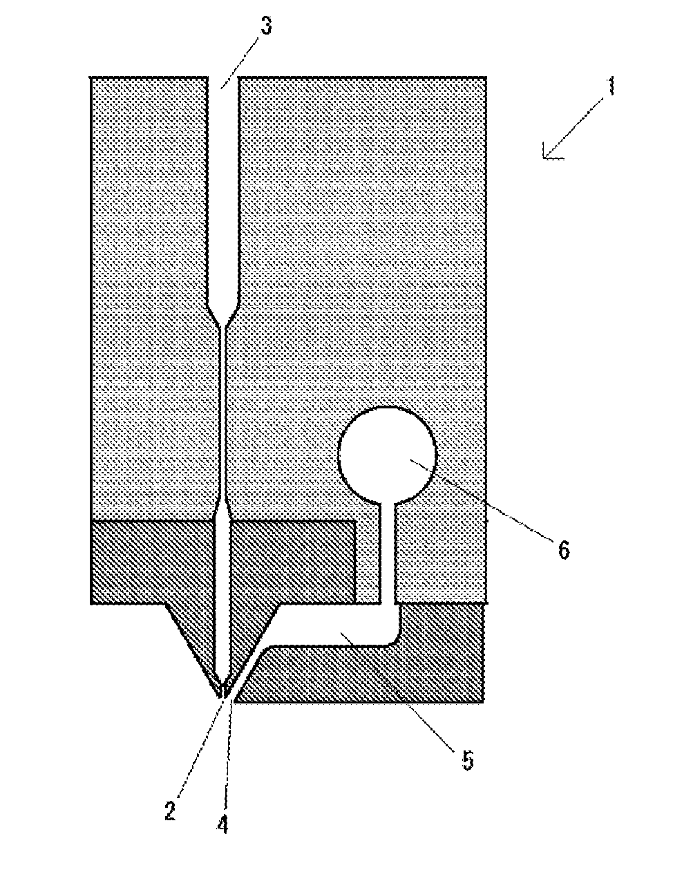
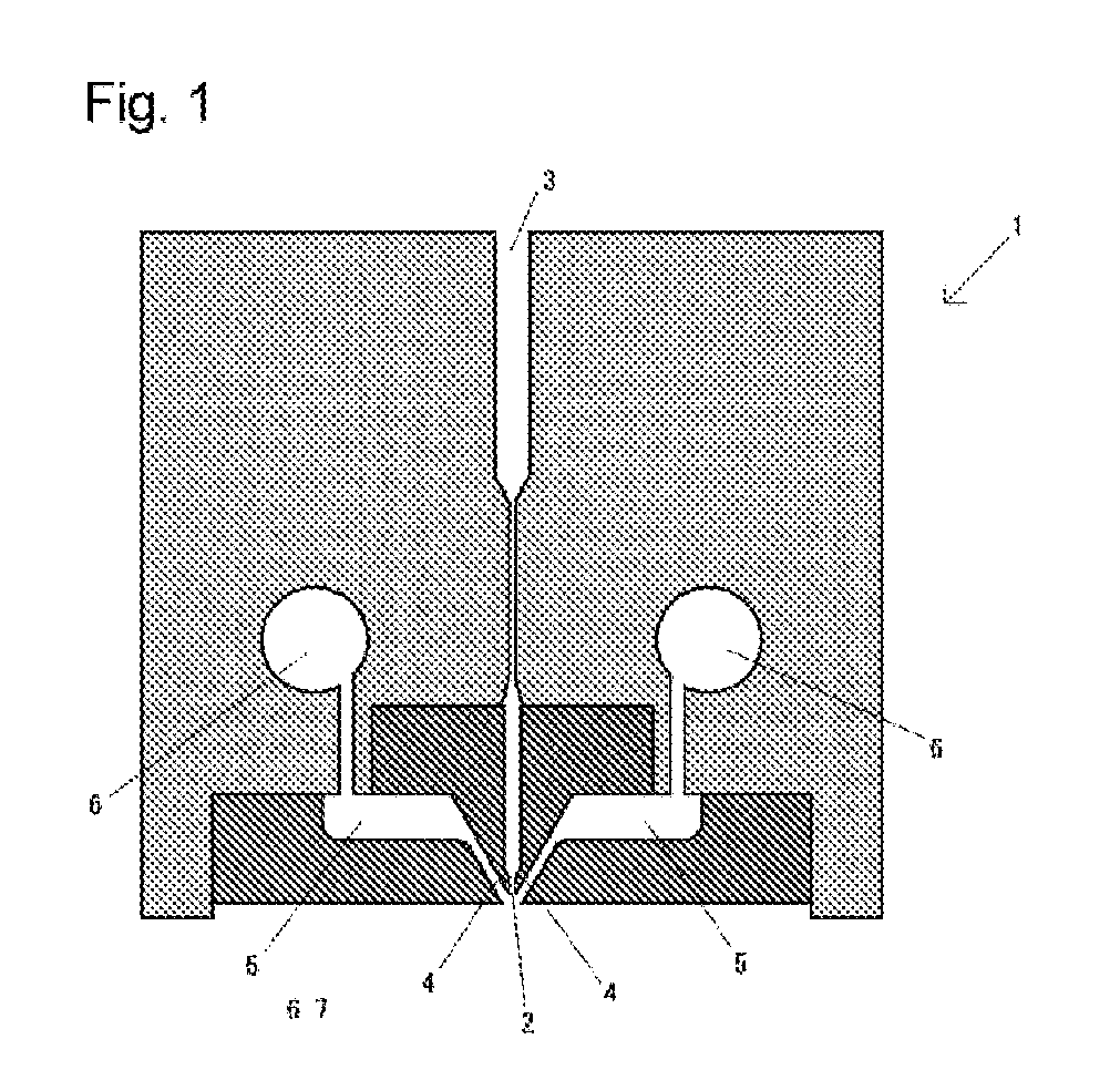
[0015]The production method of the present disclosure is conducted with using a specific spinning die. The specific spinning die may include an embodiment shown in FIG. 2. FIG. 2 shows a schematic cross sectional view of a spinning die having a cuboid shape and a direction from the front side to the back side of the paper sheet on which FIG. 2 is drawn is a longitudinal direction of the spinning die 1. A plurality of nozzle holes 2 are aligned in the longitudinal direction (the direction from the front side to the back side of the paper sheet) in a determined space distance. Thermoplastic polymer is melt blown from the nozzle holes to form ultrafine fibers.

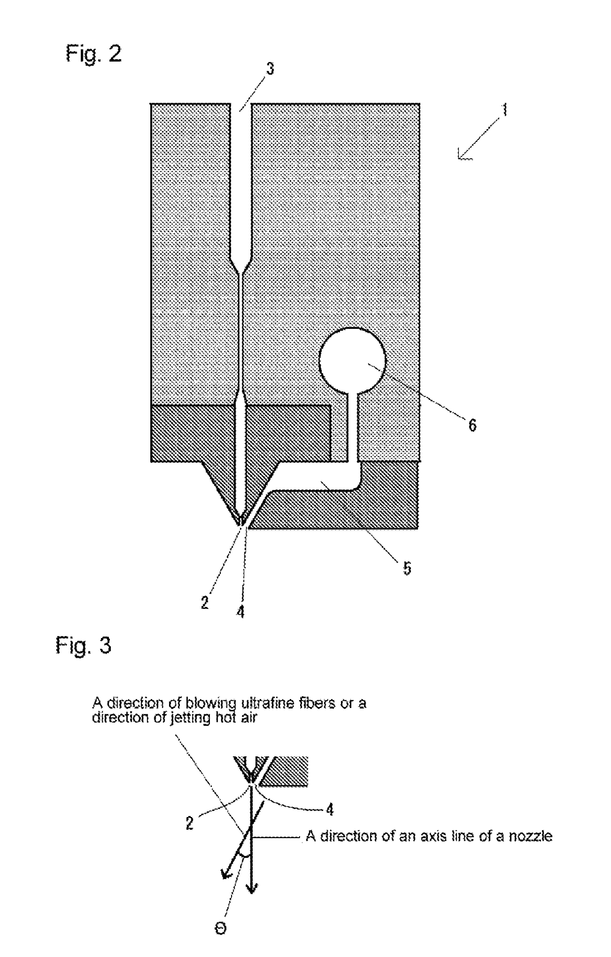
[0016]A slit is provided in only a right side of the nozzle hole 2. Hot air is flowed in pipes 6 in a pressurized condition and passed through hot air passage 5, thus jetting from slit 4. Accordingly, the ultrafine fibers from the nozzle 2 are blown to a left side to the axis line direction of the nozzle by jetting hot air. FIG. 3...


PUM

PropertyMeasurementUnit
angleaaaaaaaaaa
diameteraaaaaaaaaa
diameteraaaaaaaaaa

Abstract

A spinning die for producing ultrafine fiber nonwoven fabric is made miniaturized and its productivity thereof is enhanced. The spinning die has a substantial cuboid shape and a plurality of nozzle holes is disposed in a longitudinal direction. A slit for jetting hot air is disposed only in one side of the nozzle holes. Thermoplastic polymer is melt blown from the nozzle of the spinning die to obtain ultrafine fibers. Hot air is jetted from the slit disposed at only one side of the nozzle holes. The result is that the ultrafine fibers melt blown in a direction inclined with respect to an axis direction of the nozzle. The blown ultrafine fibers are accumulated by sucking to downward to obtain ultrafine fiber nonwoven fabric.

Description

CROSS-REFERENCE TO RELATED APPLICATIONS[0001]This application is a National Phase application filed under 35 USC 371 of PCT International Application No. PCT / JP2016 / 070580 with an International Filing Date of Jul. 12, 2016, which claims under 35 U.S.C. § 119(a) the benefit of Japanese Application No. 2015-144966 filed on Jul. 22, 2015, the entire contents of which are incorporated herein by reference.BACKGROUND(a) Technical Field[0002]The present disclosure relates to a method for producing ultrafine fiber (or filament) nonwoven fabric and an apparatus therefor, in particular to the method which has excellent productivity and the apparatus therefor with a reduced size.(b) Description of the Related Art[0003]Hitherto, ultrafine fiber nonwoven fabric has been produced with using a spinning die of a substantial cuboid shape, which has nozzle holes for melt blowing thermoplastic polymer and slits for jetting hot air in both sides of the nozzle holes. The nozzle holes are linearly arrang...

Claims


Application Information

Patent Timeline
Patent Type & Authority Applications(United States)
IPC IPC(8): D04H3/033D01D4/02D01D5/08D01D10/00D04H3/016D04H3/16
CPCD04H3/033D01D4/025D01D5/08D01D10/00D04H3/016D04H3/16D10B2505/04D10B2503/00D01D5/0985
Inventor SUEMITSU, HIROKAZUGOTO, MASAHIROHARADA, TSUYOSHI
Owner KASEN NOZURU SEISAKUSHO
Why Eureka
Try Eureka