Ultraviolet curing module
a curing module and ultraviolet light technology, applied in the field of ultraviolet curing modules, can solve the problems that the ultraviolet of the ultraviolet light emitting diode cannot quickly and efficiently cure the uv curable resin,
- Summary
- Abstract
- Description
- Claims
- Application Information
AI Technical Summary
Benefits of technology
Problems solved by technology
Method used
Image

Examples
first embodiment
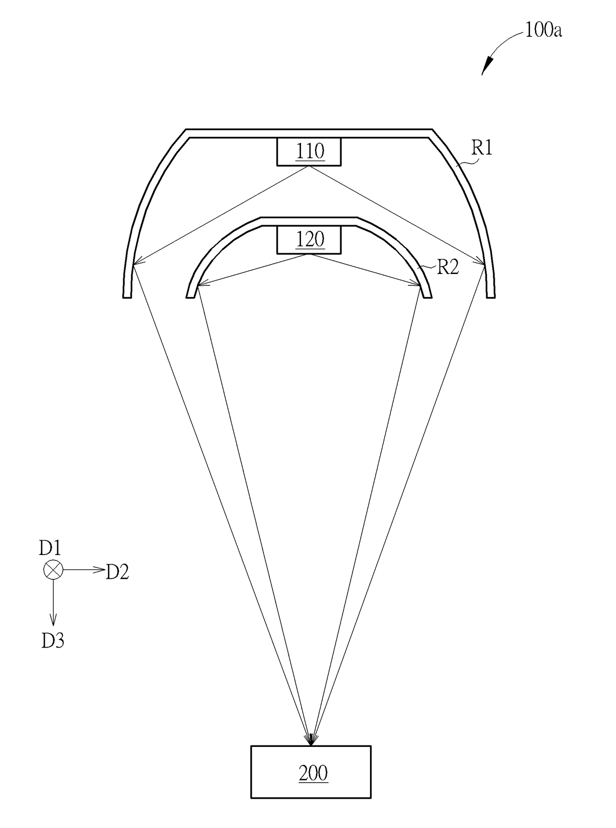
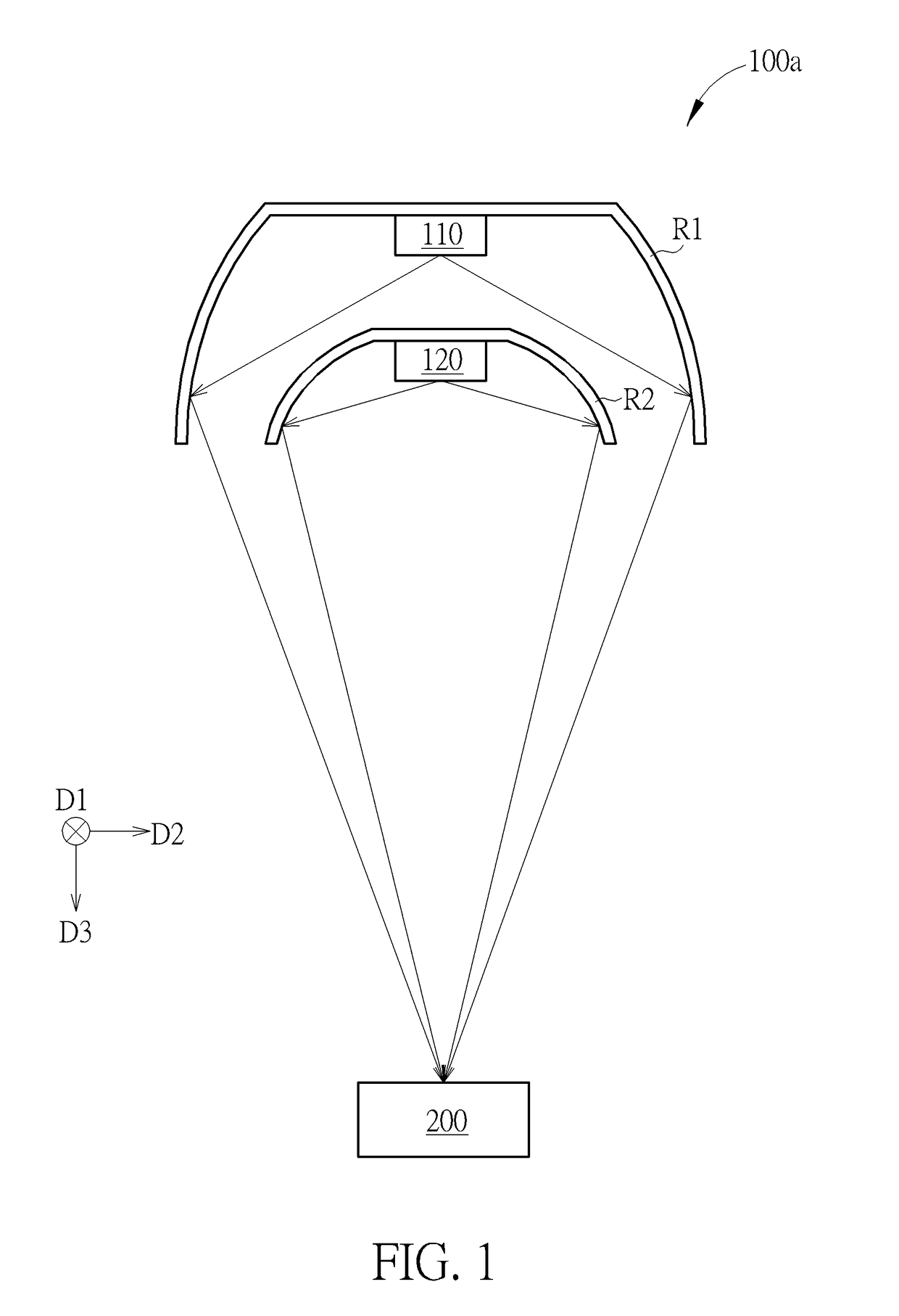
[0015]Please refer to FIG. 1. FIG. 1 is a diagram showing an ultraviolet curing module of the present invention. As shown in FIG. 1, the ultraviolet curing module 100a of the present invention comprises a first light source 110, a second light source 120, a first reflective member R1 and a second reflective member R2. The first light source 110 is configured to emit ultraviolet with a first spectrum, and the first spectrum has a first peak wavelength. The second light source 120 is configured to emit ultraviolet with a second spectrum, and the second spectrum has a second peak wavelength. For example, the first light source 110 is configured to emit ultraviolet with the first peak wavelength within an UVA waveband ranges from 315 nm to 420 nm, and the second light source 120 is configured to emit ultraviolet with the second peak wavelength within an UVC waveband ranges from 100 nm to 280 nm. In the present embodiment, a difference between the first peak wavelength and the second pea...
second embodiment
[0018]Please refer to FIG. 3. FIG. 3 is a diagram showing the ultraviolet curing module of the present invention. As shown in FIG. 3, the optical axis of the first light source 110 is not parallel to the optical axis of the second light source 120 of the ultraviolet curing module 100b, but the focal point of the first reflective member R1 overlaps the focal point of the second reflective member R2. As such, when ultraviolet of the first light source 110 and ultraviolet of the second light source 120 are respectively reflected by the first reflective member R1 and the second reflective member R2, the irradiation range of ultraviolet of the first light source 110 on the irradiated object 200 overlaps (or at least partially overlaps) the irradiation range of ultraviolet of the second light source 120 on the irradiated object 200, in order to cure the same region of the irradiated object 200. On the other hand, the curvature of the first reflective member R1 can be different from the cu...
third embodiment
[0020]Please refer to FIG. 6. FIG. 6 is a diagram showing the ultraviolet curing module of the present invention. As shown in FIG. 6, the ultraviolet curing module 100c further comprises a third light source 130 and a third reflective member R3. In the present embodiment, the third light source 130 is configured to emit ultraviolet with the first spectrum. For example, the third light source 130 is configured to emit ultraviolet having a wavelength within the UVA waveband. The third light source 130 can also emit ultraviolet with the second spectrum (such as within the UVC waveband) or emit ultraviolet with a spectrum (such as within a UVB waveband) different from the first and second spectrums in order to improve photo initial reaction of the irradiated object 200, but the present embodiment is not limited thereto. Similarly, a second optical lens (not shown in FIG. 6) can also be arranged in front of the third light source 130 for refracting ultraviolet of the third light source t...
PUM
 Abstract
Description
Claims
Application Information
 - R&D
- Intellectual Property
- Life Sciences
- Materials
- Tech Scout
- Unparalleled Data Quality
- Higher Quality Content
- 60% Fewer Hallucinations
Browse by: Latest US Patents, China's latest patents, Technical Efficacy Thesaurus, Application Domain, Technology Topic, Popular Technical Reports.
© 2025 PatSnap. All rights reserved.Legal|Privacy policy|Modern Slavery Act Transparency Statement|Sitemap|About US| Contact US: help@patsnap.com