
Developing Roller, Charging Roller, Conductive Roller and Method for Producing the Same

a technology of developing rollers and charging rollers, applied in the field of conductive rollers, can solve the problems of contaminating the photosensitive drum, faulty image, easy stacking of toners on the surface of the roller, etc., and achieves the effect of shortening or skipping a drying step, improving the charging property of toners or photosensitive drums, and improving image quality

Active Publication Date: 2008-11-27
BRIDGESTONE CORP
View PDF51 Cites 72 Cited by
  • Summary
  • Abstract
  • Description
  • Claims
  • Application Information

AI Technical Summary

Benefits of technology

[0010]Still furthermore, although the conductive roller in which the resin coating layer is disposed on the outer peripheral surface of the elastic layer is excellent in charging property to toner as compared with a conductive roller not having the resin coating layer, there is still a room for improvement and a conductive roller which is more excellent in the charging property to toner and can highly improve image quality is required.
[0012]It is, therefore, the first object of the invention to provide a developing roller and a charging roller not requiring a long drying line for mass production, hardly causing filming due to toner adhesion or rise of resistance even if it is used for a long time, and being excellent in the durability.
[0013]Also, it is the second object of the invention to provide a developing roller and a charging roller not requiring a long drying line for mass production, not contaminating a photosensitive drum, hardly causing toner filming or rise of resistance even if it is used for a long time, and being excellent in durability.
[0014]Moreover, it is the third object of the invention to provide a conductive roller such as a developing roller or the like not requiring a long drying line for mass production and grinding step of an elastic layer, and having an adequate micro-unevenness on the surface of the resin coating layer.
[0015]Furthermore, it is the fourth object of the invention to provide a conductive roller being capable of skipping or shortening a drying step in mass production, having an improved charging property against toners or a photosensitive drum as compared with a conventional one and being capable of highly improving image quality.
[0016]Still furthermore, it is the fifth object of the invention to provide a method for producing a conductive roller by forming a resin coating layer on the surface of the elastic layer through ultraviolet or electron beam irradiation, which is capable of producing a conductive roller having a high durability by improving adhesiveness between the elastic layer and the resin coating layer.

Problems solved by technology

However, the above conductive roller in which the resin coating layer comprising the ultraviolet-curing type resin is disposed on the outer peripheral surface of the elastic layer has a problem that toners are easily stacked on the surface of the roller under some use conditions because the releasing property of the surface of the roller is low.
Therefore, when an image forming apparatus incorporated with such a conductive roller is used for a long time, there is a problem that toner filming occurs on the surface of the conductive roller or surface resistance becomes high to easily cause faulty image.
Moreover, since the resin coating layer comprising the ultraviolet-curing type resin contains unreacted compound which is not cured by ultraviolet ray, it may contaminate the photosensitive drum.
Particularly, when a carbon-based electron conductive agent is compounded for controlling an electric resistance of the resin coating layer, since the carbon-based electron conductive agent absorbs ultraviolet rays, there is a problem that the unreacted compound tends to remain.
Furthermore, although the conductive roller is preferable to uniformly hold a predetermined amount of toners on its surface, when a main body of the roller is made by charging a raw material for the elastic layer into a mold in which the shaft is disposed for improving productivity of the conductive roller by skipping a grinding step, the outer peripheral surface of the elastic layer becomes smooth just like a cavity surface of the mold and there is a problem that the resin coating layer formed thereon also becomes smooth.

Method used

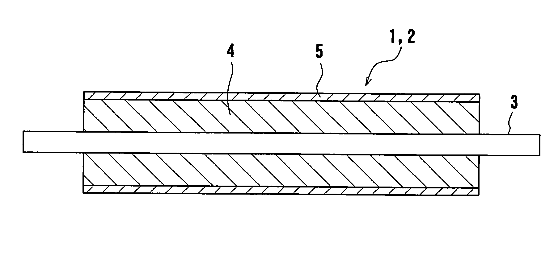
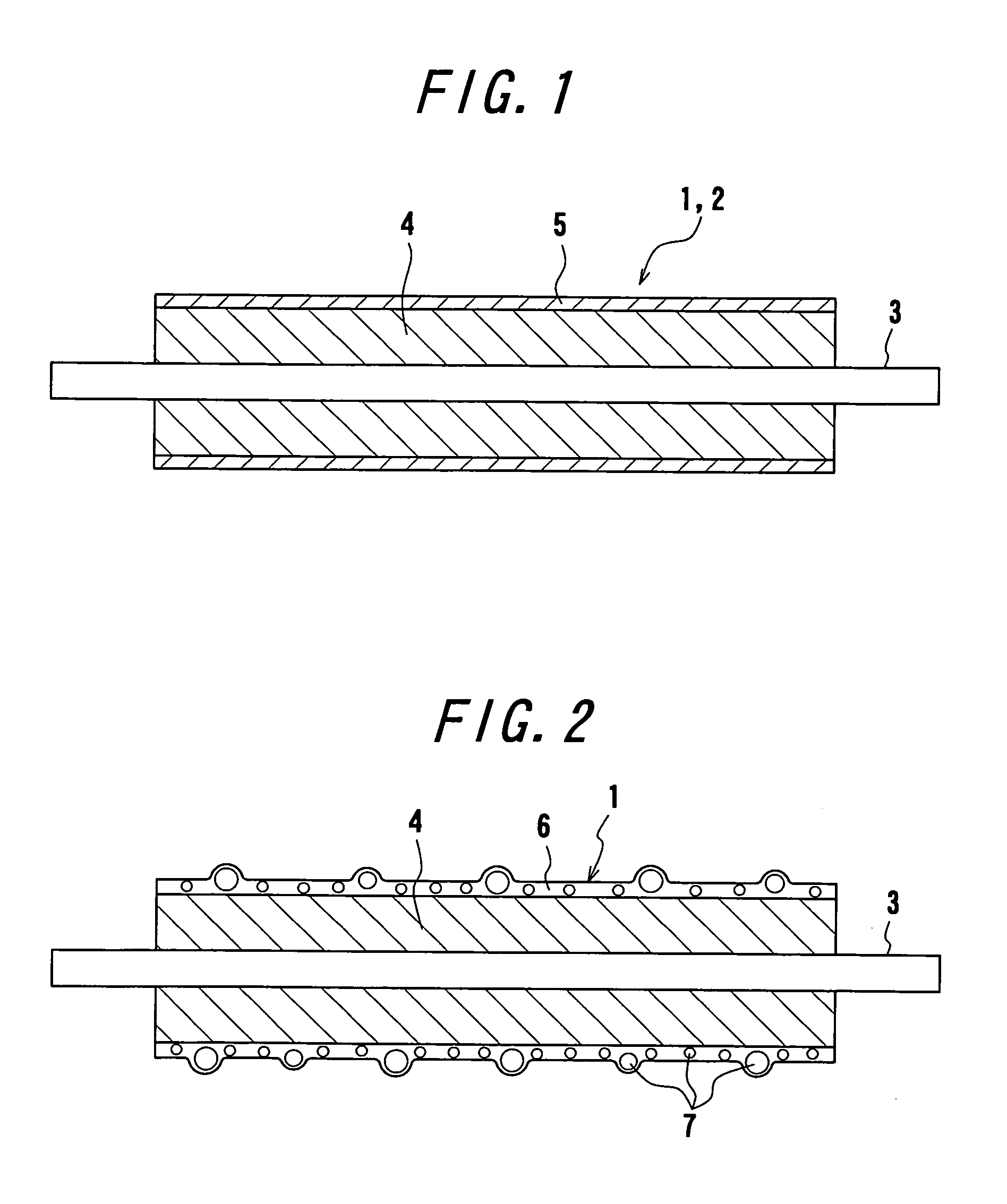
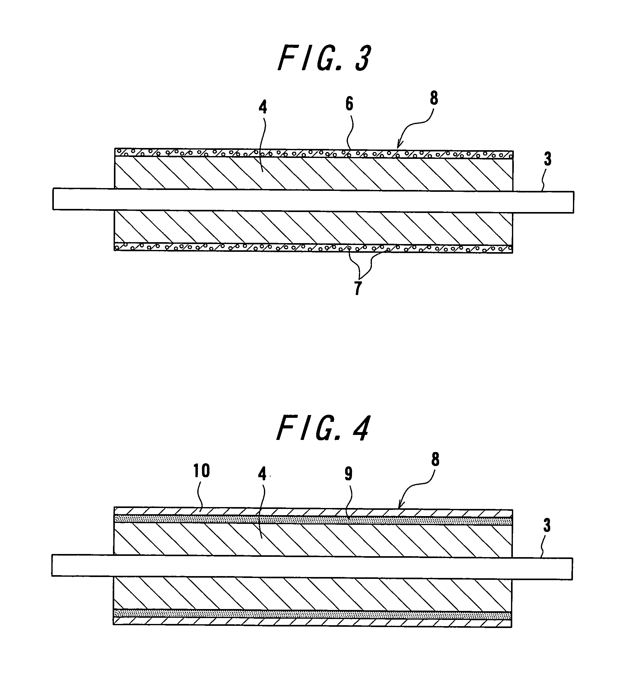

Image

  • Developing Roller, Charging Roller, Conductive Roller and Method for Producing the Same
  • Developing Roller, Charging Roller, Conductive Roller and Method for Producing the Same
  • Developing Roller, Charging Roller, Conductive Roller and Method for Producing the Same

Examples


examples

[0381]The following examples are given in illustration of the invention and are not intended as limitations thereof.

[0382]

example a-1

[0383]100 parts by mass of Sunnix FA952 [polyetherpolyol manufactured by Sanyo Chemical Industries, Ltd., OH value=37], 1 part by mass of SRX274C [foam stabilizer manufactured by Dow Corning Toray Silicone Co., Ltd.], 2.8 parts by mass of TOYOCAT NP [amine catalyst manufactured by Tosoh Corporation], 1.5 parts by mass of TOYOCAT EP [amine catalyst manufactured by Tosoh Corporation] and 59 parts by mass of SANFOAM IC-716 [tolylene diisocyanate manufactured by Sanyo Chemical Industries, Ltd.] are mechanically stirred and foamed. Then, a metal shaft having an outer diameter of 8.0 mm and a length of 240 mm is disposed into a metal cylindrical mold having an inner diameter of 16 mm, a length of 250 mm and a fluorine-processed surface through its opening and then 8.0 g of the above raw material for a polyurethane foam is charged from a foaming machine. Then, the mold charged with the raw material for the polyurethane foam is heated in an oven of 80° C. for 20 minutes and released to make...

example a-2

[0394]100 parts by mass of polyetherpolyol which is trifunctional, has a molecular weight of 9,000 and is produced by adding propylene oxide to glycerin, is added with 1.6 parts by mass of conductive carbon and 0.15 part by mass of dibutyltin dilaurate, sufficiently stirred and mixed, and then defoamed for 20 minutes with stirring under vacuum to be used as a polyol component. The polyol component has a hydroxyl value of 19 mgKOH / g. On the other hand, polypropylene glycol-modified polymeric MDI having a NCO content of 11% is defoamed for 20 minutes with stirring under vacuum and used as an isocyanate component. The polyol component and the isocyanate component are stirred at high speed and mixed by a binary type casting machine while regulating a ratio of the polyol component to the isocyanate component to be 101.75 / 13.70 (isocyanate index: 103). The mixed urethane raw material is charged into a metal cylindrical mold in which a metal shaft having an outer diameter φ of 8 mm is set ...


PUM

PropertyMeasurementUnit
volume resistivityaaaaaaaaaa
particle sizeaaaaaaaaaa

Abstract

This invention relates to a conductive roller such as a developing roller, a charging roller or the like provided with a resin coating calyer on a surface of an elastic layer, and more particularly to a conductive roller having the resin coating layer using an ultraviolet-curing type resin or an electron beam curing type resin and being obtained by contriving a structure of the resin coating layer, rendering the resin coating layer to contain microparticles, controlling the particle size of the microparticles, or forming the resin coating layer after the outer peripheral surface of the elastic layer is subjected to surface treatment.

Description

TECHNICAL FIELD[0001]This invention relates to a conductive roller such as a developing roller, a charging roller or the like and a method for producing the same, and more particularly to a conductive roller used in an image forming apparatus such as an electro-photographic apparatus, e.g. a copying machine, a printer or the like, an electrostatic recording apparatus and so on.BACKGROUND ART[0002]In an image forming apparatus of an electro-photographic system such as a copying machine, a printer or the like, a pressurized developing method is known as a developing method in which toners are supplied to a photosensitive drum or the like carrying a latent image thereon and attached to the latent image of the photosensitive drum to visualize the latent image. In the pressurized developing method, for example, development is conducted by charging the photosensitive drum at a constant electric potential, then forming an electrostatic latent image on the photosensitive drum by an exposure...

Claims


Application Information

Patent Timeline
Patent Type & Authority Applications(United States)
IPC IPC(8): G03G15/08G03G15/02
CPCG03G15/0818Y10T29/49544Y10T29/49563Y10T29/4956
Inventor AKAMA, SHUYOUANZAI, HIROYUKIKANESUGI, HIROYUKIISHIKAWA, HIKARUSAKATA, JUNJITAKAGI, KOJISUGIMURA, TAKAYUKI
Owner BRIDGESTONE CORP
Learn More