Vehicle wheel alignment apparatus and system, and related methods thereof

Inactive Publication Date: 2018-07-26
BIG RIG CUSTOM TOOLING LLC
View PDF0 Cites 0 Cited by
  • Summary
  • Abstract
  • Description
  • Claims
  • Application Information

AI Technical Summary

Benefits of technology

The present patent provides an apparatus, system, and method for aligning vehicle wheels. The system includes a frame and an optical device mounted on the frame. A non-metal shaft is positioned against the rim of the vehicle wheel, locked in place with a magnetic securing mechanism, and an optical device is used to determine the alignment of the wheel. The method also includes steps for manufacturing non-metal shaws using a 3D printing process. The technical effect of the invention is improved performance and accuracy in vehicle wheel alignment.

Problems solved by technology

When using the camera system, it is imperative that the camera is mounted precisely and correctly to the rim, since any inadvertent fluctuation or skewed mounting of the camera to the rim will hinder achieving accurate alignment measurements.
While this type of conventional alignment system has been used successfully in many applications, it has many drawbacks.
For one, when the metal shafts contact the rim face, they often scratch the rim face and routinely cause deep, visible scratches to the rim face when the magnetic lock is employed.
These scratches cannot be repaired due to the finish on the rim, so the rim must be replaced entirely, which can have a high cost, exceeding $1,000 USD in most cases.
Further, while the metal shafts are durable in some respects, they are prone to fluctuation when the magnetic lock is activated.
These forces cause inaccuracies with the position of the camera, which in turn, causes inaccuracies and unreliable measurements in the camera alignment system.
Accordingly, these inaccuracies cause vehicle wheels to be misaligned even after the camera alignment system is used.
Thus, a heretofore unaddressed need exists in the industry to address the aforementioned deficiencies and inadequacies.

Method used


Image

  • Vehicle wheel alignment apparatus and system, and related methods thereof
  • Vehicle wheel alignment apparatus and system, and related methods thereof
  • Vehicle wheel alignment apparatus and system, and related methods thereof

Examples


Embodiment Construction

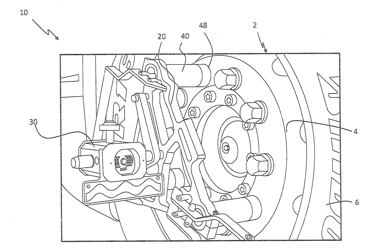
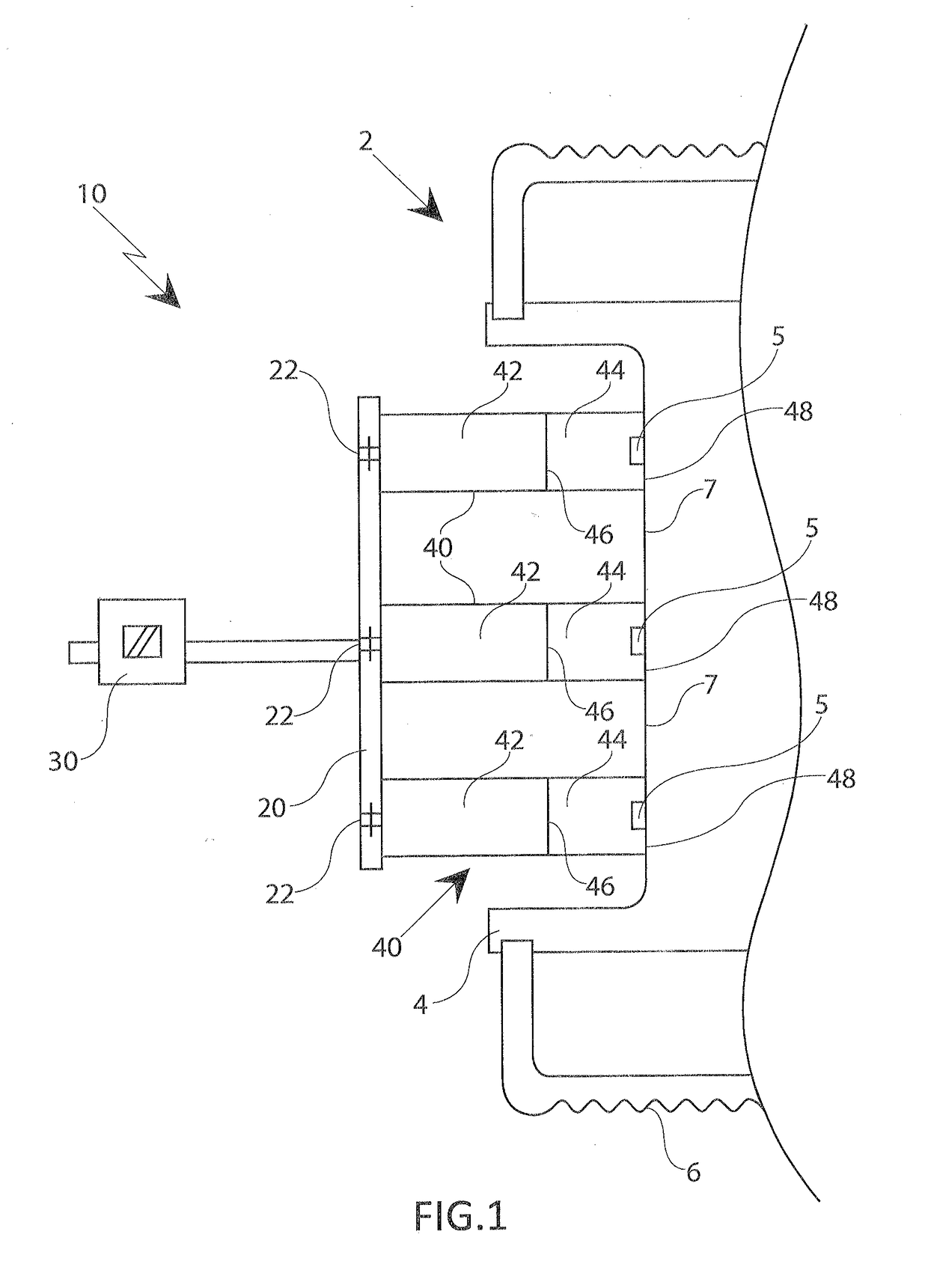
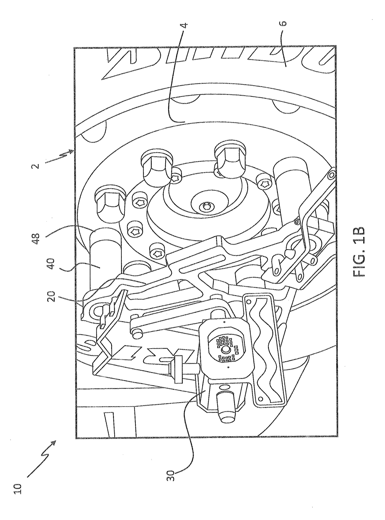
[0023]FIG. 1A is a cross-sectional illustration of a vehicle wheel alignment system 10, in accordance with a first exemplary embodiment of the present disclosure. FIG. 1B is an illustration of the vehicle alignment system 10 of FIG. 1A in use on a vehicle, in accordance with the first exemplary embodiment of the present disclosure. The vehicle wheel alignment system 10, which may be referred to simply as ‘system 10’ includes a frame member 20. An optical device 30 is mounted to the frame member 20. At least one shaft 40 is connected to the frame member 20, wherein the at least one shaft 40 is positionable against a rim 4 of the vehicle wheel 2. The at least one shaft 40 is constructed from a non-metal material.

[0024]The system 10 may have particular uses to align the wheels of vehicles to the frame of the vehicle, especially the wheels of industrial or commercial vehicles, such as large trucks, tractor trailers, mass-transit vehicles, delivery trucks, or any similar vehicle. The sys...


PUM

PropertyMeasurementUnit
Dimensionless propertyaaaaaaaaaa
Diameteraaaaaaaaaa

Abstract

A vehicle wheel alignment system has a frame member and an optical device mounted to the frame member. At least one shaft connected to the frame member, wherein the at least one shaft is positionable against a rim of the vehicle wheel, wherein the at least one shaft is constructed from a non-metal material. The system may allow for vehicle wheel alignments without scratching the face of the rim. Related methods, apparatuses, and systems are provided.

Description

CROSS REFERENCE TO RELATED APPLICATION[0001]This application claims benefit of U.S. Provisional Application Ser. No. 62 / 449,952 entitled, “Vehicle Wheel Alignment Apparatus and System, and Related Methods Thereof”, filed Jan. 24, 2017, the entire disclosure of which is incorporated herein by reference.FIELD OF THE DISCLOSURE[0002]The present disclosure is generally related to wheel alignment and more particularly is related to vehicle wheel alignment apparatus, system, and method.BACKGROUND OF THE DISCLOSURE[0003]Proper alignment of vehicle wheels is necessary to ensure safe operation of the vehicle and proper handling of the vehicle, and to prevent premature degradation of the tire. To ensure proper alignment of wheels on large trucks, such as tractor trailers, and similarly sized large vehicles, such as busses, a camera-based system is used. The camera system is first attached to the exterior side of the rim of each wheel on the vehicle. Then, various hardware and software devices...

Claims


Application Information

Patent Timeline
IPC IPC(8): G01B11/275B33Y10/00B33Y80/00B29C64/118
CPCG01B11/2755B33Y10/00B33Y80/00B29C64/118G01B2210/14G01B1/00G01B5/0004G01B2210/16
Inventor FINSTAD, CHANCE A.ASHE, DANIEL T.ASHAL, JOHN
Owner BIG RIG CUSTOM TOOLING LLC
Why Eureka
Try Eureka