Device and method of controlling machine tool, to control synchronized operation of spindle axis and feed axis

a technology of machine tools and synchronized operation, which is applied in the direction of computer control, program control, instruments, etc., can solve the problem of difficult to make the spindle axis perform a deceleration rotation at maximum capacity, and achieve the effect of maximizing the acceleration capacity of the spindle axis, reducing the cycle time of tapping process, and simple configuration

Active Publication Date: 2018-07-26
FANUC LTD
View PDF4 Cites 0 Cited by
  • Summary
  • Abstract
  • Description
  • Claims
  • Application Information

AI Technical Summary

Benefits of technology

[0007]The controller according to one aspect has a configuration wherein, when the spindle axis performs the rotational motion from the starting position to the target position, the numerical control section instructs only the total rotation amount and the maximum rotation speed, of the spindle axis, as the spindle axis command to the spindle-axis control section, and the spindle-axis control section performs, in accordance with the spindle axis command, the rotational motion by accelerating the spindle axis with the maximum power using the maximum permissible current, aiming at the maximum rotation speed, and continuously performs, based on the maximum acceleration detected during the maximum accelerated rotation as well as the sequentially detected residual rotation amount and current speed of the spindle axis, the rotational motion until the target position while decelerating the spindle axis so as to make the spindle axis reach the target position. Accordingly, it is no longer necessary to perform a parameter setting or adjustment, etc., required for the numerical control section to prepare acceleration and deceleration commands in conformity with the power characteristics of the spindle axis, and it is possible, with a simple configuration, to reduce the cycle time of a tapping process by executing an acceleration and deceleration control so as to maximize the acceleration capacity of the spindle axis. Further, the controller is configured so that, during a period when the spindle axis is decelerated by the position control to reach the target position after acceleration, the spindle axis performs the decelerated rotation at the positioning deceleration higher than a deceleration corresponding to the maximum acceleration while taking into account the mechanical loss of the drive source, and therefore, it is possible to improve the aforementioned effect of reducing the cycle time of the tapping process.

Problems solved by technology

In a configuration in which the cycle time is reduced by controlling the spindle axis so as to maximize the acceleration capacity thereof, there is concern that, during a period when the spindle axis is decelerated by a position control to reach a target position after acceleration, it becomes difficult to make the spindle axis perform a decelerated rotation at maximum capacity due to a mechanical loss caused in a drive source.

Method used


Image

  • Device and method of controlling machine tool, to control synchronized operation of spindle axis and feed axis
  • Device and method of controlling machine tool, to control synchronized operation of spindle axis and feed axis
  • Device and method of controlling machine tool, to control synchronized operation of spindle axis and feed axis

Examples


first embodiment

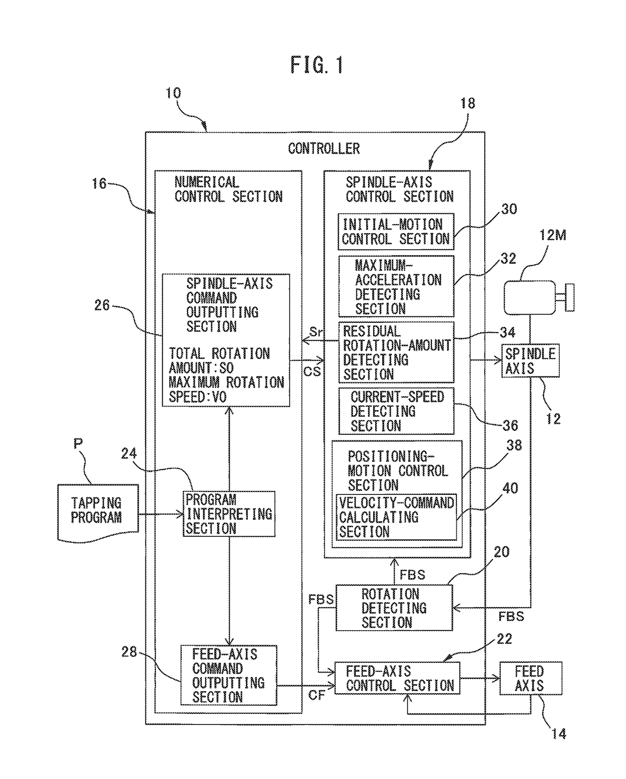
[0026]FIG. 1 is a functional block diagram depicting a configuration of a device 10 of controlling (i.e., a controller 10 of) a machine tool, according to a The controller 10 has a configuration for controlling a synchronized operation (so called a master-slave synchronization) of a spindle axis 12 and a feed axis 14, in a machine tool (e.g., a lathe, a drilling machine, a machining center, etc.) capable of performing a tapping process by the synchronized operation, in which the feed axis 14 operates to follow the rotational motion of the spindle axis 12 by taking into account a thread pitch designated by a tapping program P. The spindle axis 12 is a control axis provided for a spindle motor 12M that rotates a hold unit for holding a workpiece or a tool at a necessary speed for processing. The feed axis 14 is a control axis provided for a servo motor (not depicted) that feeds a support unit for supporting a workpiece or a tool at a necessary speed for processing. For example, in a ...

second embodiment

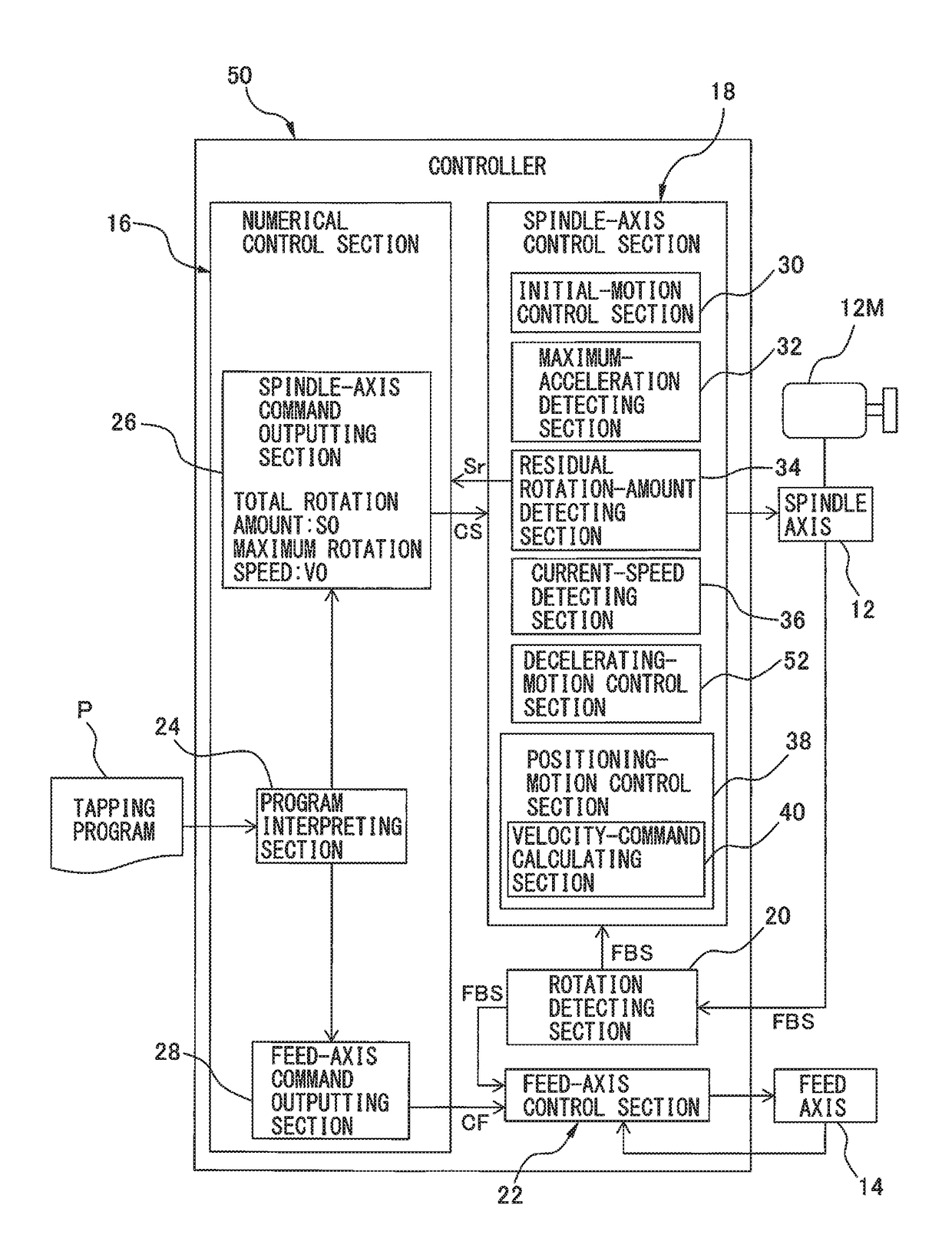
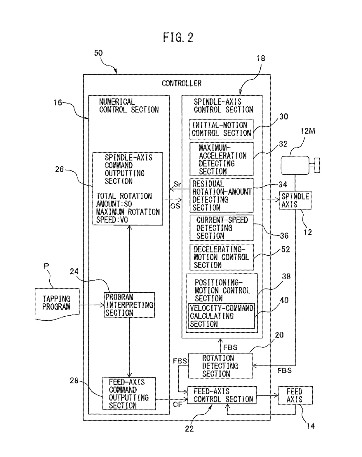
[0036]FIG. 2 is a functional block diagram depicting a configuration of a controller 50 of a machine tool, according to a The controller 50 includes, in addition to the aforementioned configuration of the controller 10, a decelerating-motion control section 52 configured to execute a velocity control for making the spindle axis 12 perform a decelerated rotation from a maximum speed in the accelerated rotation, before the positioning-motion control section 38 starts the position control. The configuration of the controller 50, other than the decelerating-motion control section 52, is analogous to that of the controller 10, and therefore corresponding components are denoted with common reference numerals and detailed descriptions thereof are not repeated.

[0037]The controller 50 includes a processor or processors, functioning as each of a numerical control section 16 configured to prepare a spindle-axis command CS and a feed-axis command CF, based on a tapping program P; a spindle-axi...


PUM


Abstract

A controller controlling a synchronized operation of spindle and feed axes. The controller is configured to make a spindle axis perform an accelerated rotation at maximum capacity from a starting position aiming at a maximum rotation speed; detect a maximum acceleration of the spindle axis; detect a residual rotation amount of the spindle axis; detect a current speed of the spindle axis; and execute a position control for making the spindle axis perform a decelerated rotation so as to reach a target position, after the accelerated rotation at maximum capacity. The controller is further configured to make the spindle axis perform the decelerated rotation at a positioning deceleration higher than a deceleration corresponding to the maximum acceleration and equal to or lower than a maximum deceleration capable of compensating for a mechanical loss in a drive source during the decelerated rotation of the spindle axis.

Description

BACKGROUND OF THE INVENTION1. Field of the Invention[0001]The present invention relates to a device of controlling a machine tool, to control a synchronized operation of a spindle axis and a feed axis. The present invention also relates to a method of controlling a machine tool, to control a synchronized operation of a spindle axis and a feed axis.2. Description of the Related Art[0002]In a machine tool capable of performing a tapping process by a synchronized operation of a spindle (or principal) axis and a feed axis, various kinds of configurations for improving processing accuracy and reducing cycle time have been proposed. For example, a thread forming apparatus that performs a tapping process by operating a feed axis to follow the rotation of a spindle axis has been known, in which a feed command value for the feed axis is computed based on the rotational speed and rotational acceleration of the spindle axis and a thread pitch, and the feed command value is corrected in accorda...

Claims


Application Information

Patent Timeline
Patent Type & Authority Applications(United States)
IPC IPC(8): G05B19/402
CPCG05B19/402G05B2219/43177G05B2219/43137G05B19/4163G05B2219/36521G05B19/4141G05B2219/50218
Inventor OKITA, TADASHIMORITA, YUUKITAJIMA, DAISUKE
Owner FANUC LTD
Why Eureka
Try Eureka