
Wireless power transmission device, and transmission power control method therefor

Pending Publication Date: 2018-07-26
GE HYBRID TECH
View PDF6 Cites 7 Cited by
  • Summary
  • Abstract
  • Description
  • Claims
  • Application Information

AI Technical Summary

Benefits of technology

The present invention provides a wireless power transmission apparatus and a power transmission control method that can maintain optimum efficiency regardless of the position of the wireless power reception apparatus, temperature, and power level without changing the system output. This means that the wireless power transmission apparatus can maintain its optimal efficiency even if the distance between the two devices changes, the temperature changes, or the power level changes. This is achieved by controlling the DC voltage or the gate bias of the inverter, instead of controlling the output of the converter during transmission power control. By excluding the DC-DC converter from the wireless power transmission apparatus, the patent aims to reduce manufacturing costs and heating.

Problems solved by technology

However, in the contact charging method, when a charger and a battery are coupled to or separated from each other, an instantaneous discharge phenomenon occurs due to a potential difference at both terminals, and since a power supply terminal is exposed to the outside, foreign substances may be piled on the power supply terminal, thereby causing a fire.
In addition, there are limitations in that the battery is naturally discharged due to moisture, and the lifetime and performance of the battery are reduced.
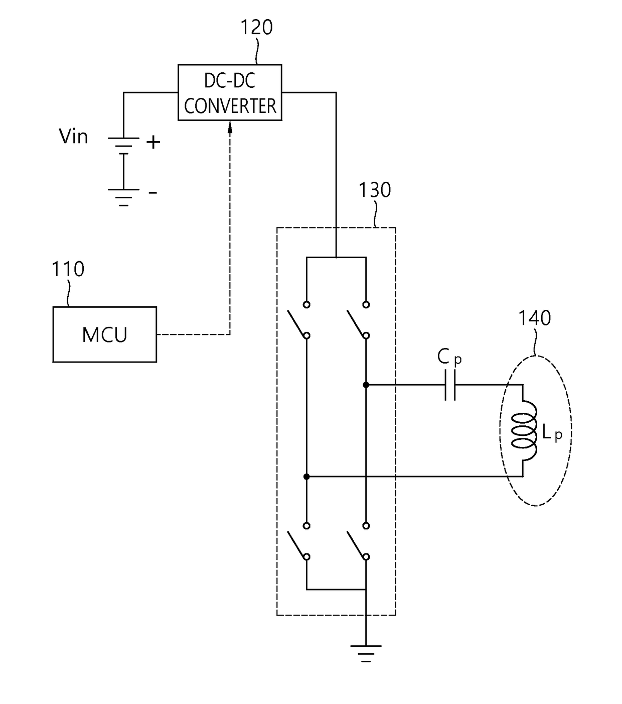
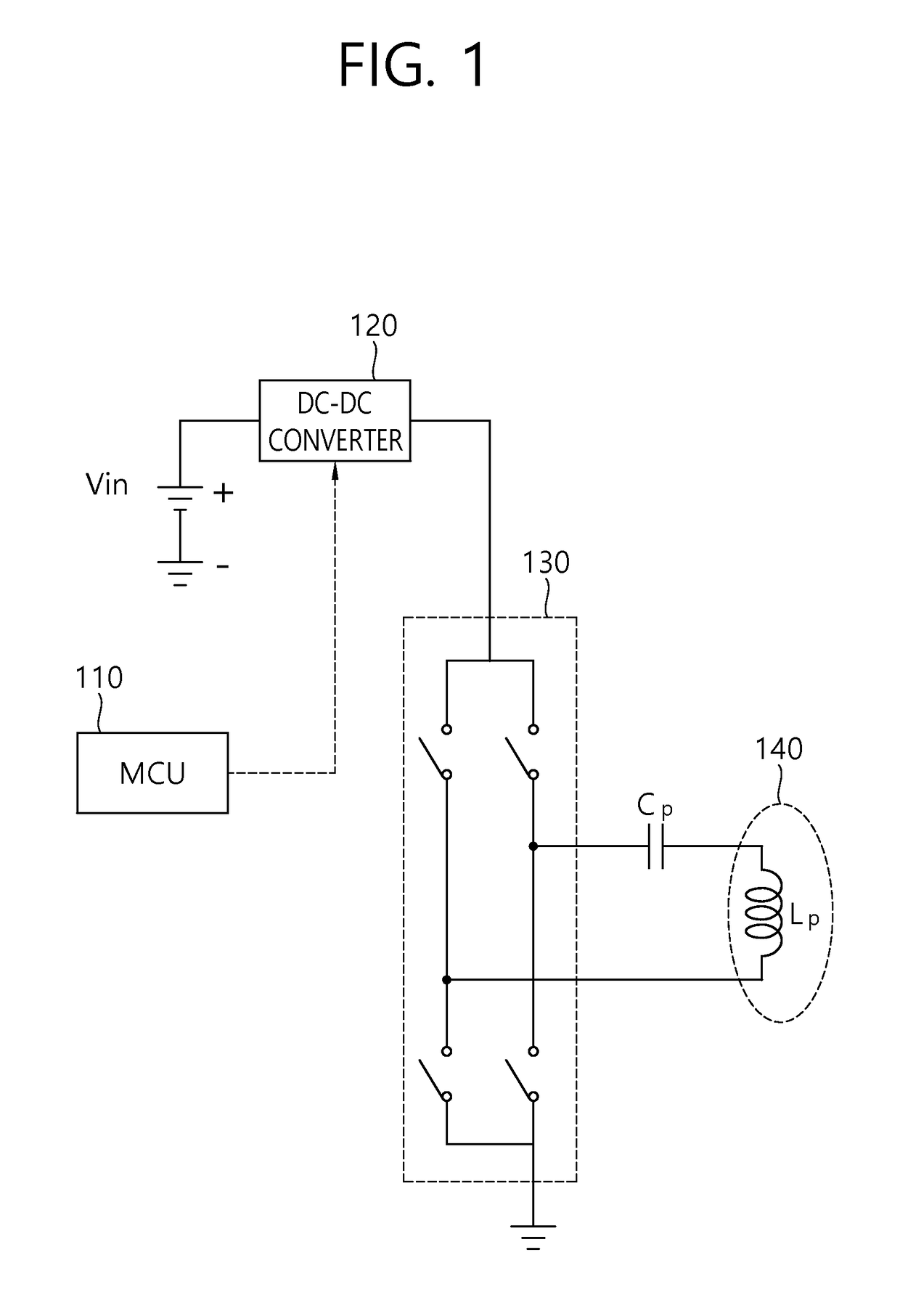
However, when the output of the DC-DC converter (120) is varied in order to control the transmission power by the wireless power reception apparatus, that is, to control the output of the inverter (130), there are limitations in that the system efficiency is reduced due to the change of the output of the wireless power transmission apparatus, heat is generated by the use of the DC-DC converter (120), the cost increases due to the presence of the DC-DC converter (120), and the additional use of a power coil is needed.

Method used


Image

  • Wireless power transmission device, and transmission power control method therefor
  • Wireless power transmission device, and transmission power control method therefor
  • Wireless power transmission device, and transmission power control method therefor

Examples


Embodiment Construction

[0031]Hereinafter, exemplary embodiments of the present invention will be described in detail with reference to the accompanying drawings so that those skilled in the art can easily carry out the present invention. However, the present invention can be implemented in various types, and is not limited to the embodiments set forth herein. Also, parts irrelevant to the description of the present invention will be omitted for clarification of description, and like parts are indicated as like reference numerals throughout the specification.

[0032]When it is described throughout the specification that one comprises (or includes or has) some elements, it should be understood that it may comprise (or include or has) only those elements, or it may comprise (or include or have) other elements as well as those elements if there is no specific limitation.

[0033]The term ‘wireless power’ used herein means any type of energy associated with an electric field, a magnetic field, and an electromagneti...


PUM


Abstract

A wireless power transmission device, and a transmission power control method therefor are provided. A wireless power transmission device for wirelessly transmitting power to a wireless power receiving device can comprise: a primary core comprising at least one primary coil and transmitting a power signal to the wireless power receiving device by being coupled, through magnetic induction or magnetic resonance, to a secondary core provided at the wireless power receiving device; an inverter connected to the primary core so as to apply an alternating voltage necessary for transmitting the power signal; and a controller connected to the inverter, and controlling a direct voltage to be applied to the wireless power transmission device and / or a gate voltage of the inverter on the basis of the information on the power received at the wireless power receiving device by the power signal.

Description

BACKGROUND OF THE INVENTIONField of the Invention[0001]The present invention relates to a contactless charging system and, more particularly, to a wireless power transmission apparatus for transmitting wireless power to a wireless power reception apparatus and a transmission power control method therefor.Related Art[0002]Recently, portable electronic devices such as a smart phone, a laptop, an MPEG-1 Audio Layer-3 (MP3) player, and a headset are spreading. However, since the portable electronic devices operate by consuming electric power stored in a battery cell (e.g., a primary battery, a secondary battery, etc.), it is necessary to charge or replace the battery cells of portable electronic devices in order to allow the portable electronic devices to continuously operate.[0003]Methods of charging battery cells are roughly divided into a contact charging method of performing charging using a power supply line and a power supply terminal and a contactless charging method of performin...

Claims


Application Information

Patent Timeline
IPC IPC(8): H02J50/12H02J50/40H02J7/02
CPCH02J50/12H02J50/40H02J7/025H02J7/342
Inventor JUNG, CHUN KILNOH, SANG YOUNKIM, HAK DO
Owner GE HYBRID TECH
Learn More