Wireless Power Charging System

a charging system and wireless technology, applied in the direction of electric vehicles, circuit monitoring/indication, transportation and packaging, etc., can solve the problems of poor charging quality, poor power transmission efficiency, and inability to immediately discharge, so as to improve the reliability and the charging capacity of the charging system and the battery pack. , the effect of improving the power transmission efficiency

Active Publication Date: 2009-10-29
GE HYBRID TECH
View PDF9 Cites 245 Cited by
  • Summary
  • Abstract
  • Description
  • Claims
  • Application Information

AI Technical Summary

Benefits of technology

[0018]The wireless power charging system of the present invention formed with the above-mentioned figures is constructed to charge battery packs or portable devices without any actual contacts among them so that there will not be any fire hazards caused by the connector contacts. A better power transmission efficiency is also expected to get since there will not be any bad connection problems due to the foreign substances among the connectors.
[0019]Since the shielding member and the eddy current reducing member are especially installed in the primary core of the wireless power transmission apparatus and the secondary core of the wireless power receiving apparatus respectively, there is an excellent effect on protecting both the charging system and the battery pack from the electromagnetic shield generated by the primary core and the secondary core.
[0020]Thus, there is an advantage of providing a reliable and better charging capacity of the charging system and the battery pack by maintaining stable temperature of the battery pack and keeping unweakened charging capacity of the battery pack even in 500 times of charge / discharge experiments.

Problems solved by technology

However, when the charger and the batteries are connected or disconnected to replenish the electric power of the batteries with this connector supply system, an instant discharge may happen because of the potential differences between the charger connector and the battery connector.
Hence the foreign substances will be gradually gathered on both connectors and finally there may be a fire disaster as well as the badly lowered charging quality.
Furthermore, since the connectors are exposed in the air, the collected humidity and dust on the connectors may cause the natural discharge of the battery.
Other problems will be involved like the declining battery life, the low battery quality, and so on.
The conventional non-contacting charging systems with the prior art can only be used to supply the electricity to the portable devices.
There are limited practical uses because they cannot be used in various alternatives.
Besides, if a metal is placed inside the effective radius of the generated magnetic field of the primary coil, there would be a lot loss of the electricity in the primary coil due to the changes of the magnetic field, so that non-contacting charging system may be damaged.
The circuit composition parts of the wireless power charging system, the portable devices and the batteries can be damaged by the existing electromagnetic field between the primary coil and the secondary coil.
The malfunction of those devices may also happen without warning.

Method used


Image

  • Wireless Power Charging System
  • Wireless Power Charging System
  • Wireless Power Charging System

Examples


embodiment

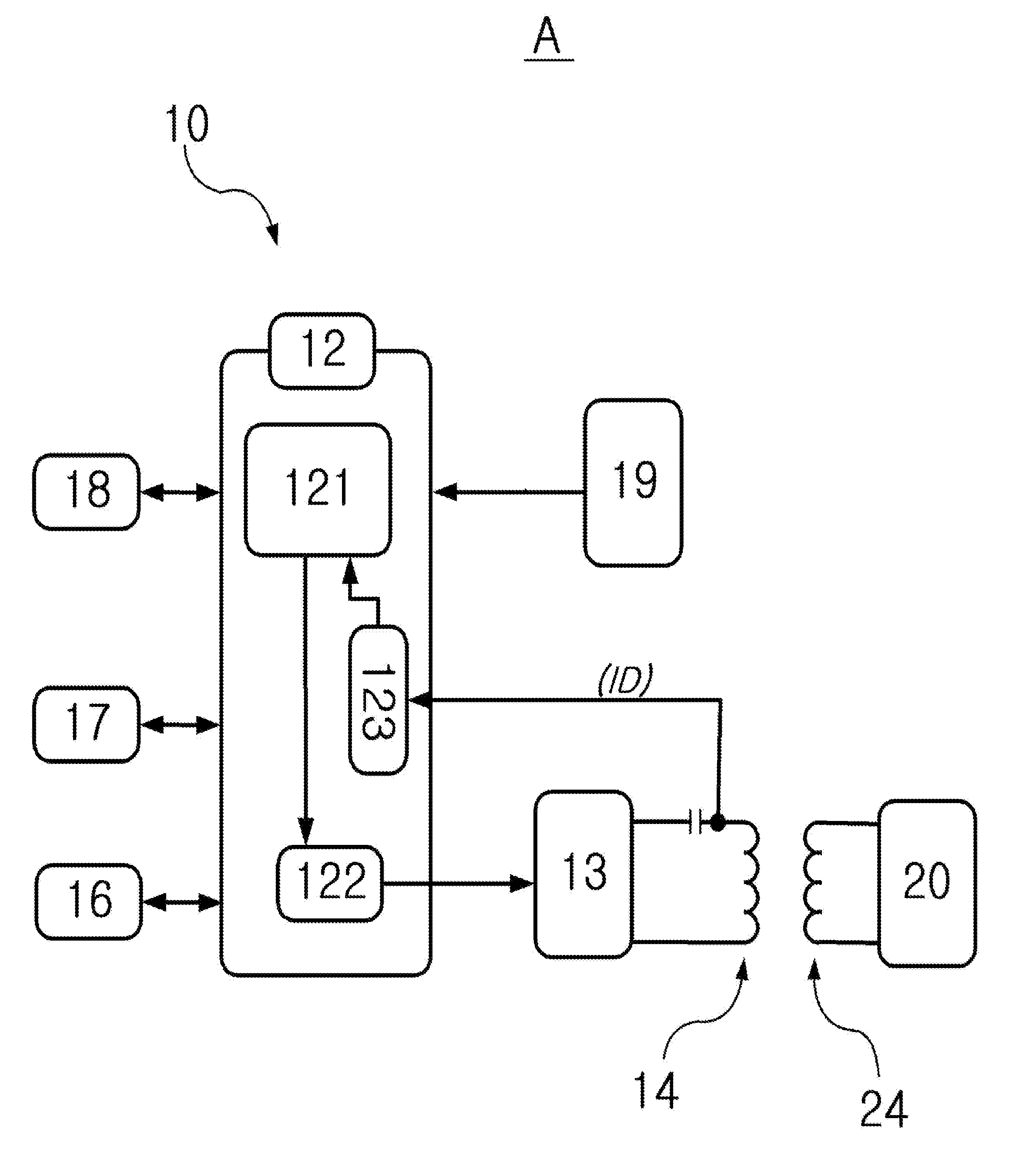
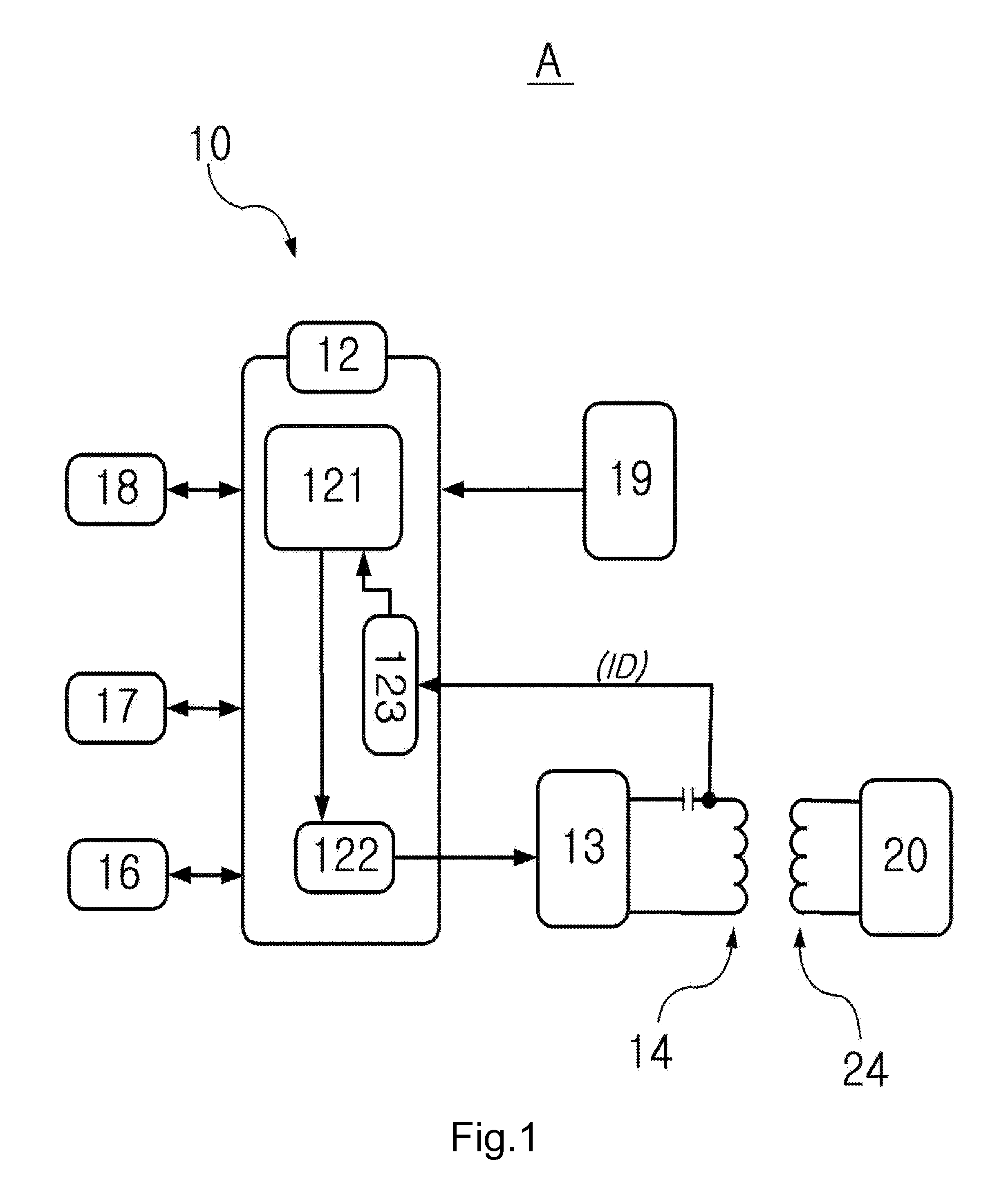
[0057]Referring to FIG. 3, in the wireless power transmission apparatus 10 of the wireless power charging system A in accordance with the present invention, the transmission shield panel 15 as a panel-shape was formed around the primary core 14 and the transmission shield panel 15 was composed of 40 parts by weight of polyurethane for every 60 parts by weight of sendust as an embodiment.

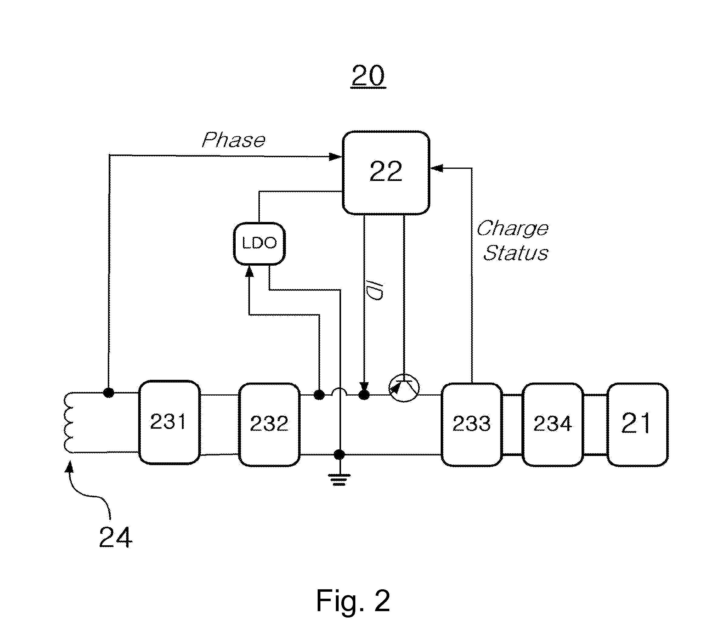
[0058]The wireless power receiving apparatus 20 was tested as being a battery pack. In the battery pack, the eddy current reducing member 26 was formed around the secondary core 24 together with the receiving shield panel 25 as a panel-shape; the receiving shield panel 25 was composed of 30 parts by weight of polyurethane for every 70 parts by weight of sendust; and the eddy current reducing member 26 was a mesh-screen polyester plated with the eddy current reducing composition consisting of 40 parts by weight of zinc for every 60 parts by weight of nickel and was also a net-shaped alloy with 135-mes...


PUM


Abstract

A non-contact power charging system includes a wireless power transmission apparatus 10 for transmitting a power signal from a primary core 14 via a resonant converter 13 by the control of a transmission control unit 12; and a wireless power receiving apparatus 20 for receiving the power signal transmitted from the primary core 14 of the wireless power transmission apparatus 10 via a secondary core 24 and charging a battery cell 21 by the control of a receiving control unit 22. The wireless power receiving apparatus 20 includes a receiving shield panel 25 and an eddy current reducing member 26 in the side of the secondary core 24 to shield an electromagnetic field generated from the secondary core 24, to thereby protect the charging system and the battery pack from the electromagnetic field.

Description

CLAIM OF PRIORITY[0001]This application claims the benefit of Korean Patent Application No. 10-2008-0039135 filed on Apr. 28, 2008, in the Korean Intellectual Property Office, the disclosure of which is incorporated herein by reference.BACKGROUND OF THE INVENTION[0002]1. Field of the Invention[0003]The present invention relates to a wireless power charging system, and more particularly, to a non-contact power charging system having a shielding member and an eddy current reducing member in primary and secondary core sides to protect both the charging system and a battery pack from the electromagnetic field.[0004]2. Description of the Related Art[0005]Portable electronic devices, such as cellular phones, personal digital assistants (PDAs), portable media players (PMPs), digital multimedia broadcasting terminal (DMB terminals), MPEG audio layer 3 (MP3) players or notebook computers, cannot be plugged into the regular power at home or office since they are generally used while the users...

Claims


Application Information

Patent Timeline
Patent Type & Authority Applications(United States)
IPC IPC(8): H02J7/04H02J7/00H02J50/00H02J50/10H02J50/70
CPCH02J7/025H02J5/005H02J7/0047H02J50/70H02J50/10H02J7/0048H02J50/12H02J7/0068
Inventor JUNG, CHUN-KIL
Owner GE HYBRID TECH
Why Eureka
Try Eureka