Pneumatic Tire

a technology of pneumatic tires and tyres, which is applied in the direction of tyre tread bands/patterns, vehicle components, transportation and packaging, etc., can solve the problems of uneven wear of corner portions formed by the zigzag shape of the main groove, adversely affecting wear resistance performance, etc., to improve braking performance, contribute to braking performance, good drainage properties

Inactive Publication Date: 2018-08-02
THE YOKOHAMA RUBBER CO LTD
View PDF6 Cites 5 Cited by
  • Summary
  • Abstract
  • Description
  • Claims
  • Application Information

AI Technical Summary

Benefits of technology

[0006]The present technology provides a pneumatic tire that can provide improved braking performance on wet road surfaces.
[0012]According to the pneumatic tire, the main grooves have a wave-like shape with periodic oscillation. This increases the overall width of the main grooves to provide good drainage properties, and allows braking performance on wet road surfaces to be improved. Furthermore, according to the pneumatic tire, the projections provided on the groove bottom of the wave-like main grooves makes the water at the groove bottom of the main groove turbulent to spread out and discharge the water out of the main groove. This allows good drainage properties to be provided and braking performance on wet road surfaces to be improved.
[0014]According to the pneumatic tire, the projections are disposed in rows in the tire lateral direction. This allows the water located outward of the main groove in the tire lateral direction to be spread out and discharged. Thus, drainage properties can be further improved and braking performance on wet road surfaces can be improved.
[0016]According to the pneumatic tire, the projections are formed with a lower projection height from the groove bottom than a wear indicator, which is a projection within the main groove that allows the degree of wear to be visually determined. This prevents the function of the wear indicator from being inhibited by the projections.
[0021]According to the pneumatic tire, the projections are disposed to provide good drainage properties in the main grooves between the middle land portions on either side of the center land portion, which is the center land portion in the center of the tread surface that contributes to the braking performance on wet road surfaces. This allows the obtained effect of improving braking performance on wet road surfaces to be significant.
[0022]A pneumatic tire according to an embodiment of the present technology can provide improved braking performance on wet road surfaces.

Problems solved by technology

The resulting difference in rigidity may adversely affect wear resistance performance.
Additionally, the corner portions formed by the zigzag shape of the main grooves may experience uneven wear.

Method used


Image

  • Pneumatic Tire
  • Pneumatic Tire
  • Pneumatic Tire

Examples


examples

[0123]In the examples, performance tests for braking performance on wet road surfaces were performed on a plurality of types of pneumatic tires of different conditions (see FIG. 9).

[0124]In these performance tests, pneumatic tires having a tire size of 205 / 55R16 were assembled on 16×6.5J rims, inflated to the regular internal pressure (200 kPa), and mounted on a test vehicle (1600 cc, front engine front wheel drive sedan passenger vehicle).

[0125]Braking performance on wet road surfaces was evaluated by measuring the braking distance of the test vehicle from a speed of 100 km / h on a wet road surface test course with a water depth of 1 mm. Then, the measurement results were expressed as index values with the value of the Conventional Example being defined as the reference (100). In this evaluation, larger values indicate less braking distance, which is preferable.

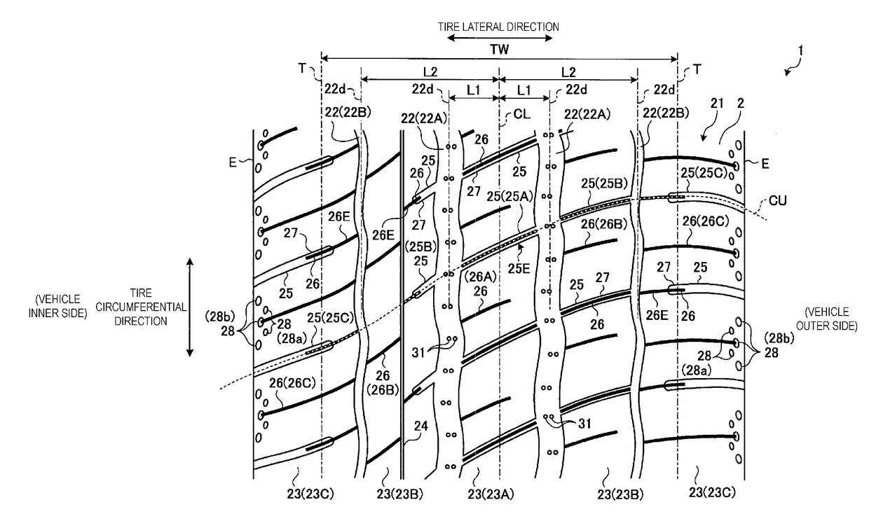
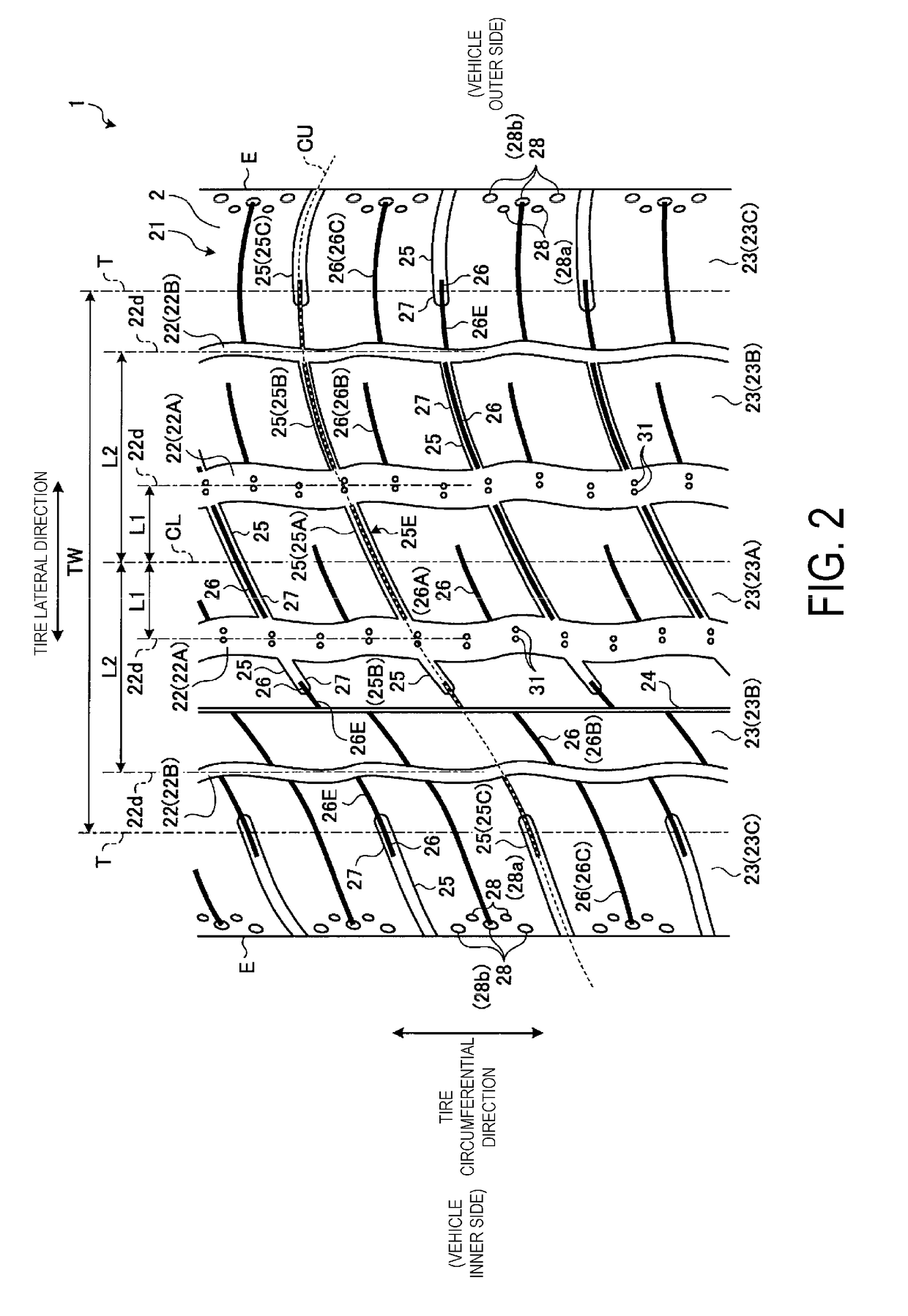
[0126]In FIG. 9, the pneumatic tires that were used as the test tires had a configuration including five land portions form...


PUM


Abstract

A pneumatic tire comprises a tread portion; a plurality of main grooves extending in a tire circumferential direction in a tread surface of the tread portion, at least one of the plurality of main grooves having a wave-like shape with periodic oscillation; a plurality of land portions adjacent to one another in a tire lateral direction formed by the plurality of main grooves; and a plurality of projections disposed on a groove bottom of the wave-shaped main groove disposed in a row in the tire circumferential direction in accord with periodic oscillations of the wave-shaped main groove.

Description

TECHNICAL FIELD[0001]The present technology relates to a pneumatic tire that can provide improved braking performance on wet road surfaces.BACKGROUND ART[0002]The conventional pneumatic tire described in Japanese Unexamined Patent Application Publication No. 2014-076764, for example, is designed to improve both wet performance (braking performance on wet road surfaces) and noise performance (anti-external noise performance). This pneumatic tire includes a plurality of wave-shaped circumferential grooves extending in the tire circumferential direction with left and right groove walls having a wave-like shape with a wavelength and an amplitude, and at least one row of wave-shaped land portions defined by adjacent wave-shaped circumferential grooves. The shape of the left and right groove walls of the wave-shaped circumferential grooves have identical wavelengths but with a phase difference. The groove wall on the wave-shaped land portion side of one of the left and right wave-shaped c...

Claims


Application Information

Patent Timeline
Patent Type & Authority Applications(United States)
IPC IPC(8): B60C11/03B60C11/01B60C11/12B60C11/13
CPCB60C11/0304B60C11/01B60C11/1236B60C11/13B60C2011/013B60C11/032B60C11/125B60C11/1281B60C11/1392B60C11/24B60C2011/0346B60C2011/0348B60C2011/0381B60C2011/1209B60C2011/1213B60C2011/1361B60C11/03B60C11/1353
Inventor KURIYAMA, MASATOSHI
Owner THE YOKOHAMA RUBBER CO LTD
Why Eureka
Try Eureka