Brake unit

a technology of brake unit and brake unit, which is applied in the direction of braking system, braking components, transportation and packaging, etc., can solve the problems of inability to control the brake system of us 2010/147633 a1 when a failure occurs on the controller, and the redundancy system to increase the reliability of the brake system mounted on the automobile is not available, so as to improve the reliability of the brake unit and the vehicle, and improve the reliability of the autonomous vehicl

Active Publication Date: 2018-08-02
TOYOTA JIDOSHA KK
View PDF0 Cites 19 Cited by
  • Summary
  • Abstract
  • Description
  • Claims
  • Application Information

AI Technical Summary

Benefits of technology

[0023]Further, any one of the brake system of the front side and the rear side may be mounted on the vehicle to serve as an inboard brake. According to the embodiment, therefore, an unsprung load of the vehicle may be reduced in comparison with that in the conventional vehicle in which the brake device is attached to the wheel.
[0024]Furthermore, the first sensor comprises the first stroke sensor and the first pedal force sensor, and the second sensor comprises the second stroke sensor and the second pedal force sensor. Those sensors are arranged in different portions of the brake pedal and the reaction force generating mechanism. According to the embodiment, therefore, two different brake sensors may be formed by the stroke sensors and the pedal force sensors. For this reason, a reliability of the brake unit may be improved. In addition, the stroke and the pedal force of the brake pedal may be detected by the sensor functioning properly even if a failure occurs on any of the sensors.
[0025]In addition, in the event of failure of the first brake system, the second brake system may control the brake force instead of first brake system entirely or partially. According to the embodiment, therefore, reliability of not only the brake unit but also the vehicle may be improved. Further, the brake unit according to the embodiment of the present disclosure may be mounted on an autonomous vehicle. In this case, an operating mode of the autonomous vehicle may be shifted promptly from an autonomous mode to a manual mode in the event of failure during autonomous operation. For this reason, the reliability of the autonomous vehicle may also be improved.

Problems solved by technology

However, a redundant system to increase reliability of the brake system mounted on automobiles together with the motor drive unit is not available in the prior art.
For this reason, the brake systems of US 2010 / 147633 A1 may not be controlled when a failure occurs on the controller.

Method used


Image

  • Brake unit
  • Brake unit
  • Brake unit

Examples


Embodiment Construction

)

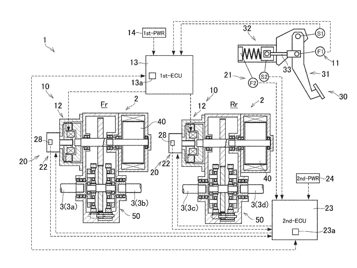
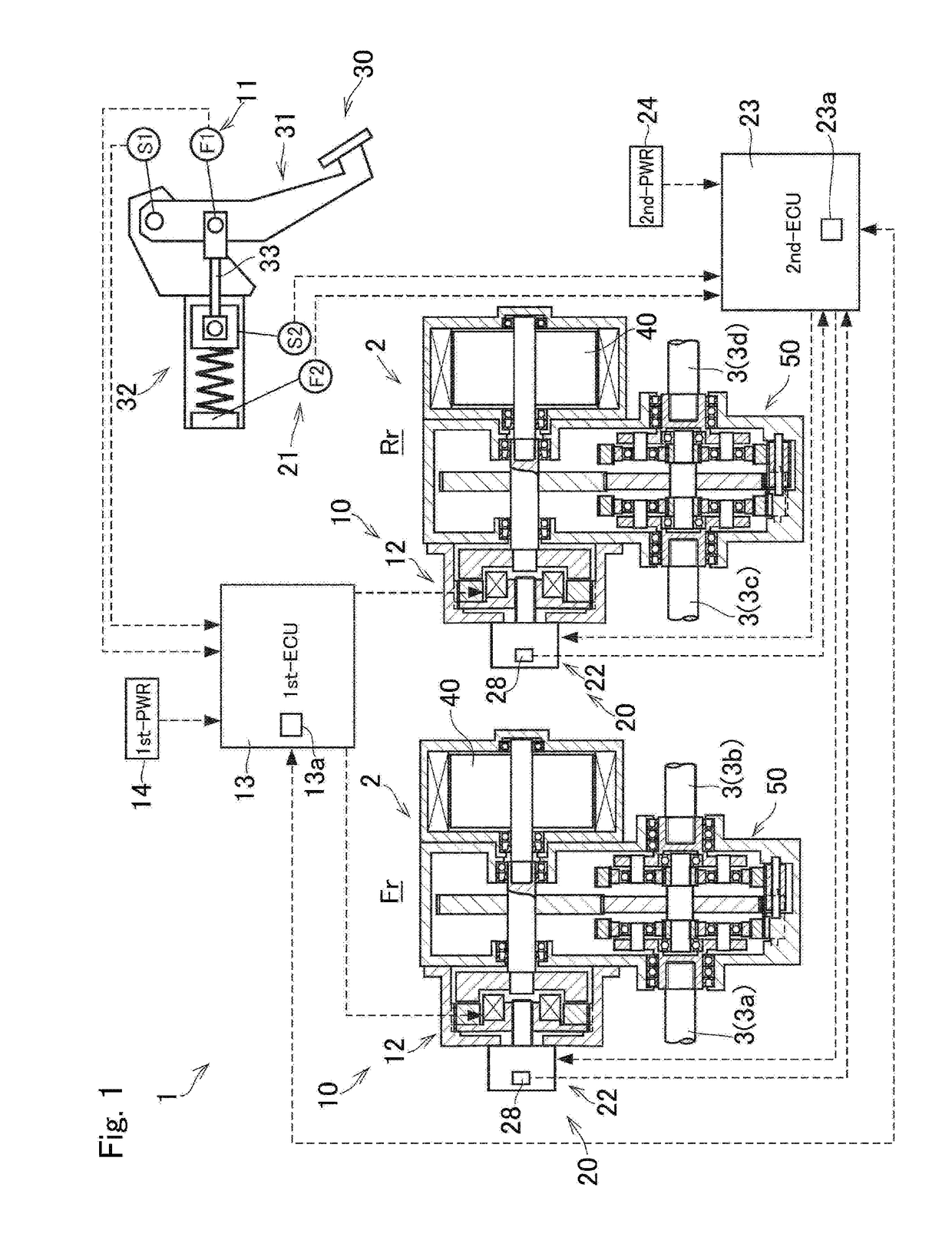
[0034]Embodiments of the present disclosure will now be explained with reference to the accompanying drawings. Referring now to FIG. 1, there is schematically shown a structure of a brake unit 1 that is mounted on a vehicle together with a motor drive unit 2. The brake unit 1 is adapted to control a brake force applied to the vehicle in response to a braking operation executed by a driver.

[0035]The brake unit 1 comprises a first brake system 10, a second brake system 20 and a pedal mechanism 30. The first brake system 10 comprises a first sensor 11, a first brake mechanism 12, a first controller 13 and a first power source 14. The second brake system 20 comprises a second sensor 21, a second brake mechanism 22, a second controller 23 and a second power source 24. The pedal mechanism 30 comprises a brake pedal 31, a stroke simulator 32, and an operation rod 33.

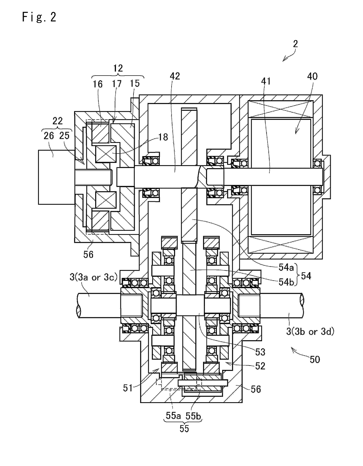
[0036]The motor drive unit 2 comprises a drive motor 40 as a prime mover that generates a drive torque, and a power transmis...


PUM


Abstract

A brake unit that allows the vehicle to evacuate safely in the event of brake failure while maintaining a braking performance. The brake unit is mounted on a vehicle together with a motor drive unit 2 to control brake force in accordance with a stroke of a brake pedal and a pedal force. Each brake system comprises: a stroke sensor; a pedal force sensor; a brake mechanism applying brake force to a driveshaft; a controller controlling the brake mechanism based on the stroke and the pedal force; and a powersource supplying electricity to the brake mechanism and the controller. The first controller 13 and the second controller support each other to control brake force.

Description

CROSS REFERENCE TO RELATED APPLICATIONS[0001]The present disclosure claims the benefit of Japanese Patent Application No. 2017-013282 filed on Jan. 27, 2017 with the Japanese Patent Office, the disclosure of which are incorporated herein by reference in its entirety.BACKGROUNDField of the Disclosure[0002]Embodiments of the present application relate generally to the art of a brake unit that establishes a brake force in accordance with a stroke of a brake pedal, and especially to an electric brake unit mounted on a vehicle together with a drive unit including a drive motor serving as a prime moverDiscussion of the Related Art[0003]US 2004 / 256911 A1 and US 2010 / 147633 A1 describe examples of a brake device used in automobiles. The braking device taught by US 2004 / 256911 A1 includes a hydraulic brake and an electric brake according to the teachings of US 2004 / 256911 A1, in the event of failure of the electric system, the function of the hydraulic brake is kept to be normal. By contrast...

Claims


Application Information

Patent Timeline
Patent Type & Authority Applications(United States)
IPC IPC(8): B60T13/74B60T13/66B60T8/34
CPCB60T13/741B60T13/748B60T13/667B60T8/345B60T2270/402B60T7/042B60T7/06B60T8/4081B60T8/409B60T8/321B60T8/3255B60T1/062B60T17/22
Inventor ISONO, HIROSHI
Owner TOYOTA JIDOSHA KK
Why Eureka
Try Eureka