Eureka AIR delivers breakthrough ideas for toughest innovation challenges, trusted by R&D personnel around the world.

Apparatus and Methods For Focussing Electrons

a technology of electron focus and apparatus, applied in the direction of multiplier electrode arrangement, multiplier dynodes, electron multiplier details, etc., can solve the problem of reducing the effective sensitive area or skewed response across the sensitive area, mismatch between the desired sensitive input area and the sensitive area, and different areas of the ion impact surfa

Active Publication Date: 2018-08-02
ETP ION DETECT PTY LTD
View PDF0 Cites 2 Cited by
  • Summary
  • Abstract
  • Description
  • Claims
  • Application Information

AI Technical Summary

Benefits of technology

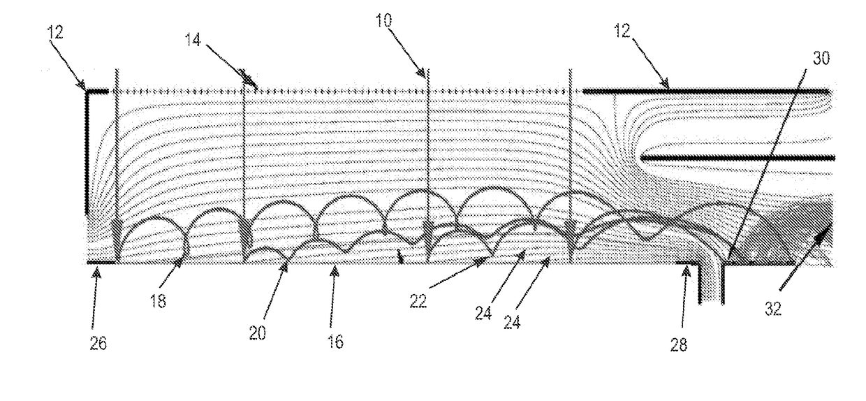
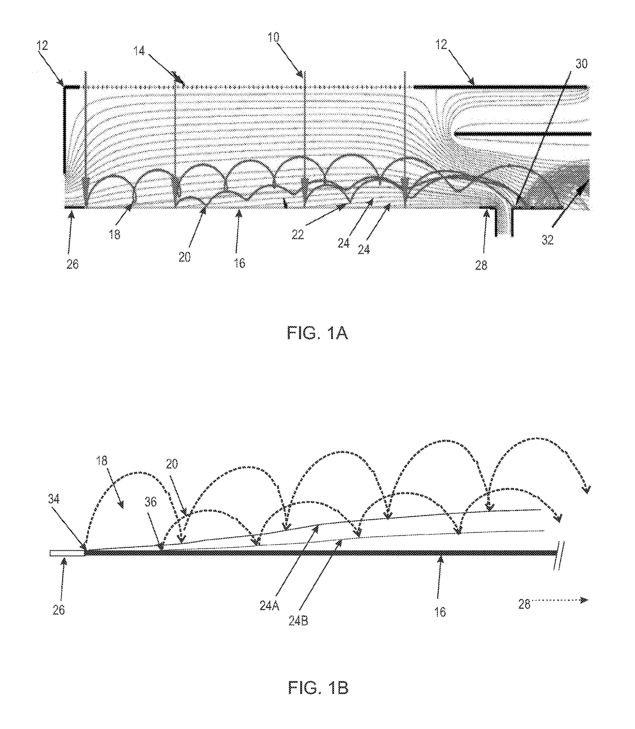
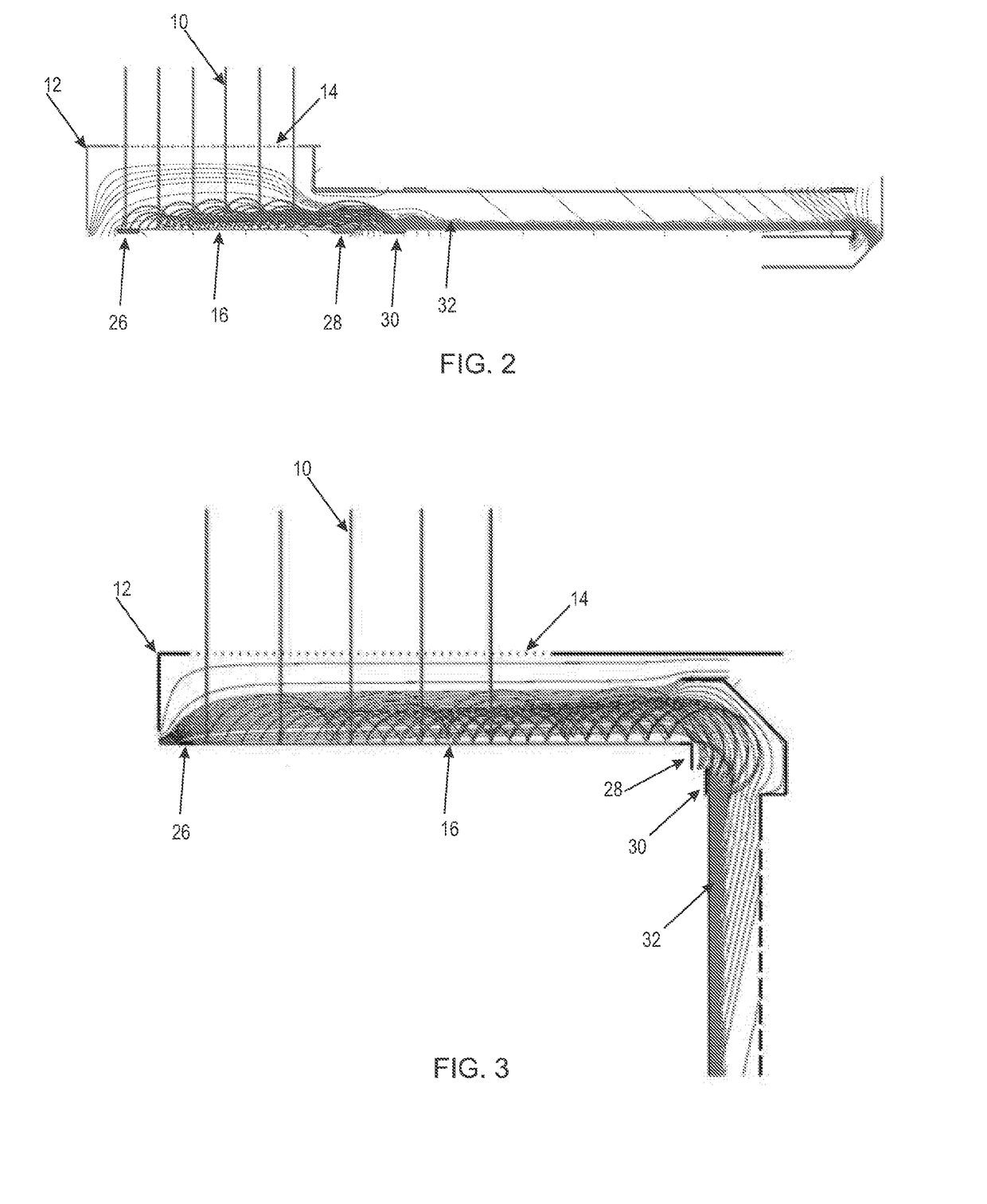
The patent describes an apparatus that prevents the loss of emitted electrons from the device. This is achieved by using a magnetic field that does not over-focus the electron, and by creating an electrical potential gradient within the emissive material that leads to a negative potential in the direction of the electron target. This prevents the electron from hitting the surface and escaping the device.

Problems solved by technology

This requirement often results in a mismatch between the desired sensitive input area and the sensitive area of the amplifying section of the electron multiplier (which is generally significantly smaller).
A problem of some electrostatic / magnetic cross field electron multipliers of the prior art is that different areas of the ion impact surface exhibit different gains.
A detector utilizing this arrangement has a very large variation in gain from one end to the other of its ion impact surface and hence its ion input aperture and in effect a significantly reduced effective sensitive area or a skewed response across its sensitive area.
This solves the gain variation problem but introduces yet a further problem.
Because secondary electron emission follows a Poisson distribution for the probability of an emission, using a low average yield leads to a significant probability of no emission at all.
Clearly, this solution is unacceptable for many applications.
A disadvantage of this system is the need for a large and complex magnetic circuit.
A further problem of the art is that secondary electrons may be reabsorbed into the impact surface.
As discussed supra, this results in the detector having a very large variation in gain from one end to the other of its ion impact surface and in effect a significantly reduced effective sensitive area or a skewed response across its sensitive area.

Method used


Image

  • Apparatus and Methods For Focussing Electrons
  • Apparatus and Methods For Focussing Electrons
  • Apparatus and Methods For Focussing Electrons

Examples


Embodiment Construction

[0052]After considering this description it will be apparent to one skilled in the art how the invention is implemented in various alternative embodiments and alternative applications. However, although various embodiments of the present invention will be described herein, it is understood that these embodiments are presented by way of example only, and not limitation. As such, this description of various alternative embodiments should not be construed to limit the scope or breadth of the present invention. Furthermore, statements of advantages or other aspects apply to specific exemplary embodiments, and not necessarily to all embodiments covered by the claims.

[0053]Throughout the description and the claims of this specification the word “comprise” and variations of the word, such as “comprising” and “comprises” is not intended to exclude other additives, components, integers or steps.

[0054]Reference throughout this specification to “one embodiment” or “an embodiment” means that a ...


PUM


Abstract

An apparatus for generating and focusing electrons is provided. The apparatus has an emissive material configured to emit an electron, an electron target, and an electrical potential gradient generator configured to generate an electrical potential gradient within the emissive material. The electrical potential gradient is oriented so as to vary from positive to negative in the general direction toward the electron target. In operation, an electron emitted from the emissive materials is deflected away from the emissive material and generally toward the electron target. The apparatus may be incorporated in scientific analytical equipment such as an electron multiplier.

Description

FIELD OF THE INVENTION[0001]The present invention relates generally to components of scientific analytical equipment. More particularly, the invention relates to apparatus and methods for focussing of electrons onto a target electrode.BACKGROUND TO THE INVENTION[0002]In many scientific applications, it is necessary to focus an electron signal. For example, in a mass spectrometer the analyte is ionized to form a range of charged species. The resultant ions are then separated according to their mass-to-charge ratio, typically by acceleration and exposure to an electric or magnetic field. The separated ions impact on an ion detector to generate a signal. Results are displayed as a spectrum of the relative abundance of detected ions as a function of the mass-to-charge ratio.[0003]The impact of an input ion on the impact surface of a detector may be amplified in some manner, typically by an electron multiplier. Generally the impact surface is incorporated within the electron multiplier. ...

Claims


Application Information

Patent Timeline
IPC IPC(8): H01J43/10H01J43/14
CPCH01J43/10H01J43/14
Inventor STRESAU, RICHARD
Owner ETP ION DETECT PTY LTD
Why Eureka
Eureka Blog
Learn More