Eureka AIR delivers breakthrough ideas for toughest innovation challenges, trusted by R&D personnel around the world.

Battery wiring module

a wiring module and battery technology, applied in secondary cells, battery components, battery service/maintenance, etc., can solve the problems of overcurrent continuously flowing in the voltage sensing wire, battery deterioration or damage, etc., and achieve the effect of easy charging/discharging control and the like for the cell

Active Publication Date: 2018-08-02
AUTONETWORKS TECH LTD +4
View PDF1 Cites 15 Cited by
  • Summary
  • Abstract
  • Description
  • Claims
  • Application Information

AI Technical Summary

Benefits of technology

The present invention provides a circuit configuration with electric current limiting elements and voltage sensing wires on an FPC. By overcoating the connection portion between the electric current limiting elements and voltage sensing wires with insulating resin, dew drops and other factors are prevented from causing short-circuits. This ensures that the voltage sensing wires are protected from overcurrent. The electric current limiting elements are also installed near the connection members, reducing the likelihood of short-circuits between adjacent voltage sensing wires. Additionally, the circuit allows for easy installation and protection against overcurrent, facilitating battery charging and discharging control. Overall, the invention provides a reliable and safe circuit configuration for protecting voltage sensing wires and ensuring proper control of the battery.

Problems solved by technology

When the plurality of cells are connected in series or in parallel, if the battery characteristics, such as battery voltage, are not uniform between the cells, problems such as battery deterioration or damage may result.
Accordingly, two voltage sensing wires may be short-circuited due to a trouble in the external circuit.
If two voltage sensing wires are short-circuited, cells may be short-circuited, causing an overcurrent to flow in the voltage sensing wires continuously.
However, when the vehicle is placed in a high humidity environment, for example, dew condensation may occur on the FPC constituting the battery wiring module and provided with the electric current limiting element.
Short-circuiting of the cell-side electrodes of the two electric current limiting elements results in a short-circuiting of two voltage sensing wires on the cell side of the electric current limiting elements, and the electric current limiting elements for the short-circuited voltage sensing wires fail to function.
In this case, the voltage sensing wires cannot be protected from the overcurrent.

Method used


Image

  • Battery wiring module
  • Battery wiring module
  • Battery wiring module

Examples


first embodiment

[0026]the present invention will be described with reference to FIG. 1 to FIG. 6.

1. Configuration of Battery Module

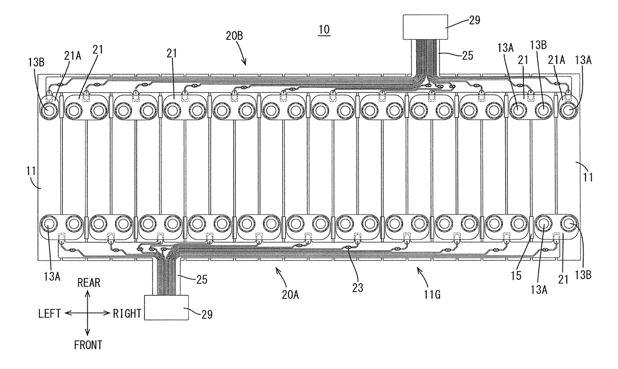
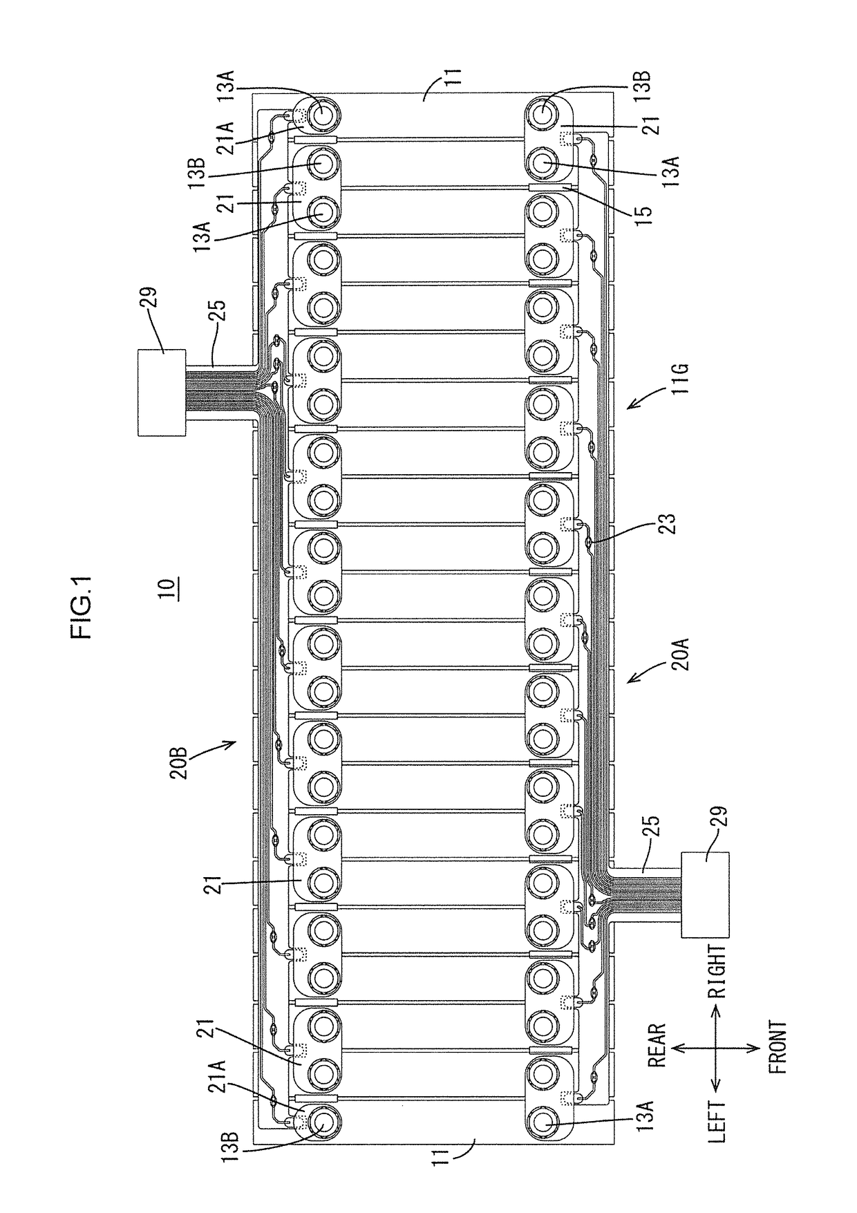
[0027]A battery module 10 according to the present embodiment is used as a drive source for electric vehicles, hybrid vehicles and the like, for example. The battery module 10 includes a cell group 11G which includes a plurality (22 in the present embodiment) of cells 11 arranged side by side each including a positive pole electrode terminal 13A and a negative pole electrode terminal 13B; and a battery wiring module 20 attached to the cell group 11G. In the following, the front indicated in FIG. 1 corresponds to the front of the battery module 10, and the rear indicated in FIG. 1 corresponds to the rear of the battery module 10. The left indicated in FIG. 1 corresponds to the left of the battery module 10, and the right indicated in FIG. 1 corresponds to the right of the battery module 10.

[0028]Between two adjacent cells 11, 11 is disposed a resin separator (not shown)....


PUM


Abstract

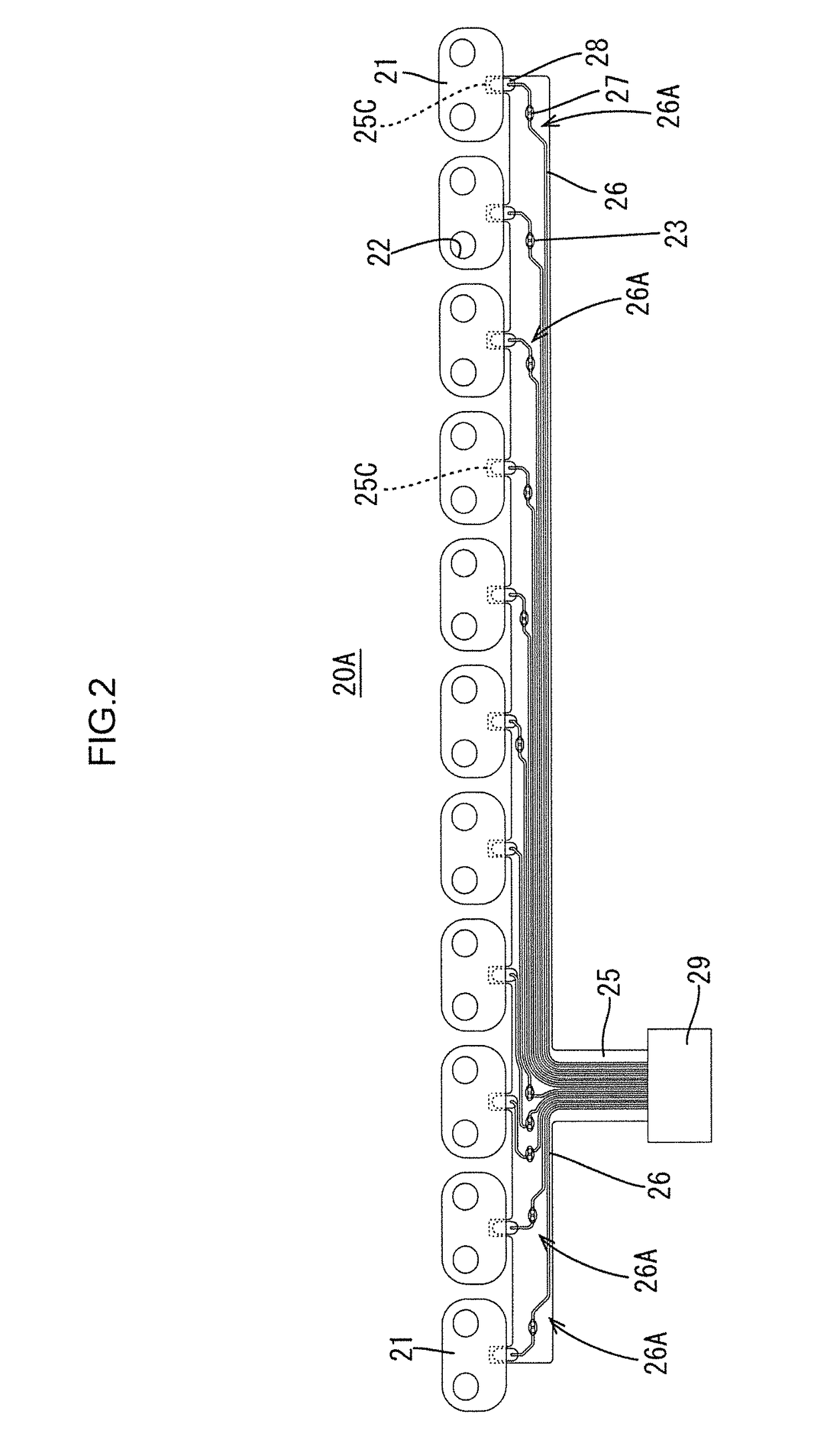
A battery wiring module is attached to a cell group including an arrangement of a plurality of cells having positive pole and negative pole electrode terminals. The battery wiring module is provided with: a plurality of connection members connecting the positive pole and negative pole electrode terminals of adjacent cells of the plurality of cells; and a flexible printed board including a plurality of voltage sensing wires for sensing voltages of the plurality of cells via the plurality of connection members. Each of the voltage sensing wires has an electric current limiting element provided somewhere therealong to limit a flow of overcurrent in the voltage sensing wires. The electric current limiting element is connected to the voltage sensing wires at a portion which is overcoated with an insulating resin.

Description

BACKGROUNDField of the Invention[0001]The present invention relates to a battery wiring module, and particularly to the short-circuit protection for wiring included in a battery wiring module.Description of the Related Art[0002]In battery modules for electric vehicles and hybrid vehicles, a number of cells are connected side by side in order to increase output. The electrode terminals of adjacent cells may be connected by connection members, such as bus bars, so as to connect a plurality of cells in series or in parallel. When the plurality of cells are connected in series or in parallel, if the battery characteristics, such as battery voltage, are not uniform between the cells, problems such as battery deterioration or damage may result.[0003]Accordingly, in battery modules for vehicles, in order to terminate charging or discharging before abnormality is caused in the voltages between the cells, each connection member is fitted with a voltage sensing wire for sensing the voltages o...

Claims


Application Information

Patent Timeline
IPC IPC(8): H01M2/20H01M2/34H01M10/48H01M50/507H01M50/519
CPCH01M2/206H01M2/348H01M10/48H01M2220/20H01M10/482H01M50/507H01M50/519H01M2200/00H01M2200/103H01M2200/106Y02E60/10H01M10/425H01M2010/4271H01M50/581
Inventor TAKASE, SHINICHIMATSUMURA, NOBUYUKIUCHITA, TOSHIFUMISUZUKI, YUSUKEKATAYAMA, JUNTA
Owner AUTONETWORKS TECH LTD
Why Eureka
Eureka Blog
Learn More