Self-pouring mold system and method of fire-proofing, repairing, and reinforcing using the same

a mold system and self-pouring technology, applied in fireproofing, auxillary members of forms/shuttering/falseworks, manufacturing tools, etc., can solve the problems of not using the open upper portion, not easy to check whether the concrete is solid, and not easy to manage the quality of the concr

Active Publication Date: 2018-08-09
KOREA INST OF CIVIL ENG & BUILDING TECH
View PDF0 Cites 4 Cited by
  • Summary
  • Abstract
  • Description
  • Claims
  • Application Information

AI Technical Summary

Benefits of technology

[0015]The present invention is directed to a self-pouring mold system and a method of fire-proofing, repairing, and reinforcing using the same that is capable of effectively pouring concrete by allowing an upper surface of the mold to correspond to a pouring surface while a pouring pipe installed to pass through a mold from a rear side of the mold to a front side thereof is lifted using a pouring pressure of concrete filled from a lower portion of the mold so that concrete is effectively poured and is capable of confirming whether the concrete is uniformly poured by whether the concrete bleeds so that construction and quality management for concrete fireproofing is possible.
[0016]Also, the present invention is directed to a self-pouring mold system and method of fire-proofing, repairing, and reinforcing using the same that is capable of effectively pouring concrete by allowing a pouring pipe installed to pass through a mold from a rear side of the mold to a front side thereof to be lifted using a pouring pressure of concrete filled from a lower portion of the mold so that an upper surface of the mold corresponds to a pouring surface.
[0017]According to an aspect of the present invention, there is provided a self-pouring mold system which allows a pouring pipe installed to pass through a mold from a rear side of the mold to a front side thereof to pour concrete from a lower portion of the mold so that concrete is uniformly poured without bleeding to have fire-proofing of the concrete. The self-pouring mold system includes a self-pouring apparatus installed to pass through a front panel block out part (S3) formed on the mold, a pouring pipe installed on the front side of the mold so that concrete (C) is poured through the self-pouring apparatus from the rear side of the mold, and a concrete pumping apparatus installed using an extension pipe member, wherein the mold includes a mold frame part including a central vertical opening part (S1) in which reinforcing ribs are horizontally and vertically separated from each other and intersect each other, the front panel block out part (S3) formed so that a whole front panel part is coupled to a front side thereof, and a finishing plate-upper opening part (S4) allowing the horizontal pouring finishing plate to be horizontally inserted between an upper surface of the front panel part and a lower surface of an upper plate of the mold frame part so that, when a worker pulls a horizontal hook part of the horizontal pouring finishing plate toward a rear side of the mold, a horizontal finishing plate is inserted into the finishing plate-upper opening part (S4) so that the horizontal pouring finishing plate is not exposed to the front side of the mold.
[0018]According to another aspect of the present invention, there is provided a method of fire-proofing, repairing, and reinforcing using a self-pouring mold system including (a) providing a self-pouring mold system (A), (b) supplying concrete to a pouring pipe using a concrete pumping apparatus, and (c) inserting a vertical pouring finishing plate of a self-pouring apparatus toward a rear side of a mold, wherein the self-pouring mold system A in operation a includes a self-pouring mold apparatus installed to pass through a front panel block out part (S3) formed on the mold, and a pouring pipe installed so that concrete C is poured toward a front side of the mold from a rear side of the mold through the self-pouring mold apparatus, wherein the self-pouring mold apparatus includes a horizontal pouring finishing plate including a horizontal finishing plate set to the front side of the mold, and a horizontal hook part extending from the horizontal finishing plate toward the rear side of the mold through the front panel block out part (S3), vertical guide units transversely separated from each other on the rear side of the mold so that the front panel block out part (S3) is positioned as an opening, and installed to extend vertically, a vertical pouring finishing plate set to the front side of the mold to finish the front panel block out part (S3) so that the horizontal hook part is supported on an upper side thereof from the rear side of the mold, and formed so that the pouring pipe passes therethrough, and a middle pouring pipe bracket positioned by both vertical guide units and set to be in contact with a rear side of the vertical pouring finishing plate so that the horizontal hook part is supported on an upper side thereof from the rear side of the mold, and formed so that the pouring pipe passes therethrough, when concrete is supplied to the pouring pipe, the concrete (C) is poured toward the front side of a front panel part of the mold and rises, and the horizontal pouring finishing plate is lifted by a concrete pouring pressure, and thus, the method allows fire-proofing of the concrete to be performed by allowing the concrete to be poured from a lower portion of the mold using the pouring pipe installed to pass through the mold from the rear side thereof to the front side thereof to be uniformly poured without bleeding.

Problems solved by technology

However, in some cases, the open upper portion is not used due to interference by an existing concrete structure.
In this case, it is not easy to check whether the concrete is poured to be airtight by visual inspection, and it is not easy to manage the quality of the concrete because the concrete is poured toward the sides.

Method used


Image

  • Self-pouring mold system and method of fire-proofing, repairing, and reinforcing using the same
  • Self-pouring mold system and method of fire-proofing, repairing, and reinforcing using the same
  • Self-pouring mold system and method of fire-proofing, repairing, and reinforcing using the same

Examples


Embodiment Construction

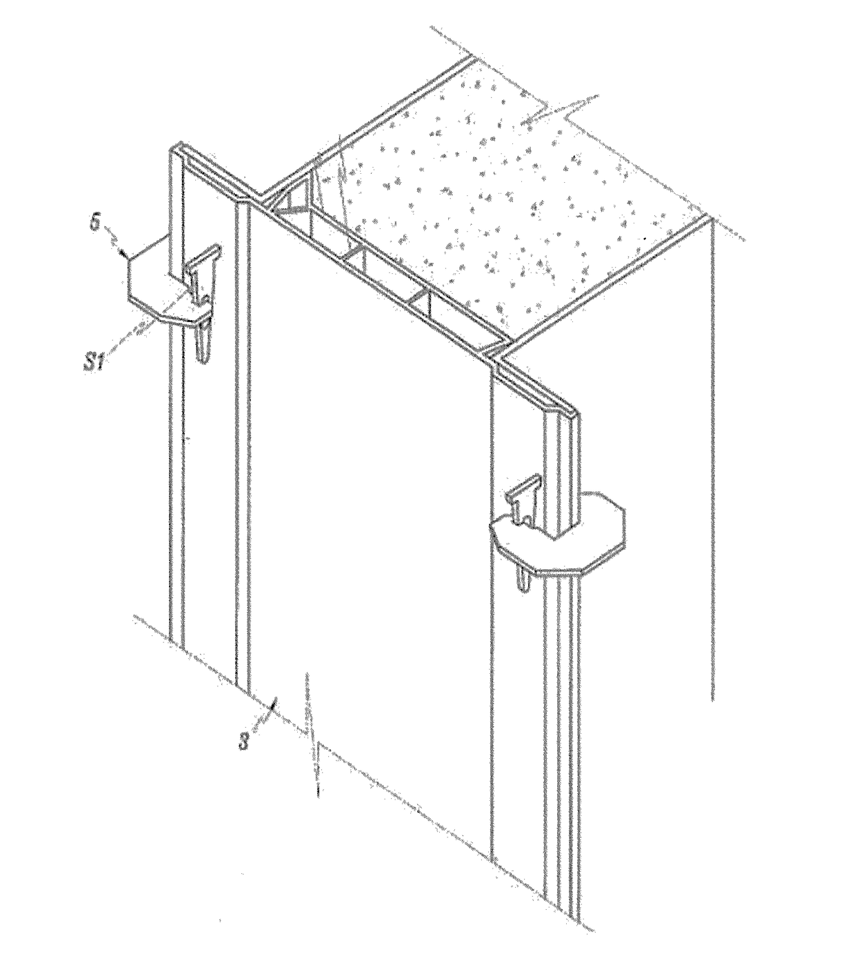
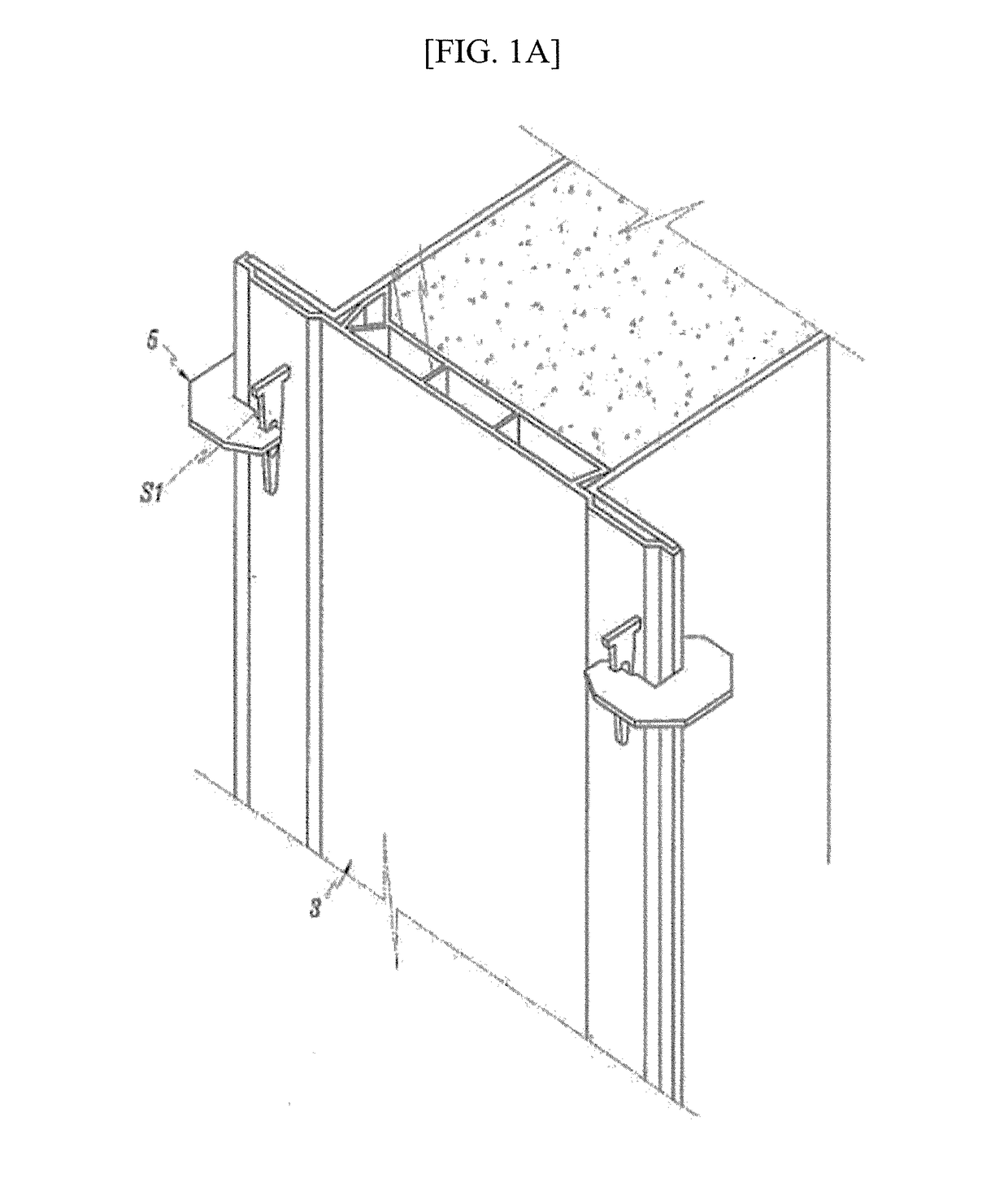
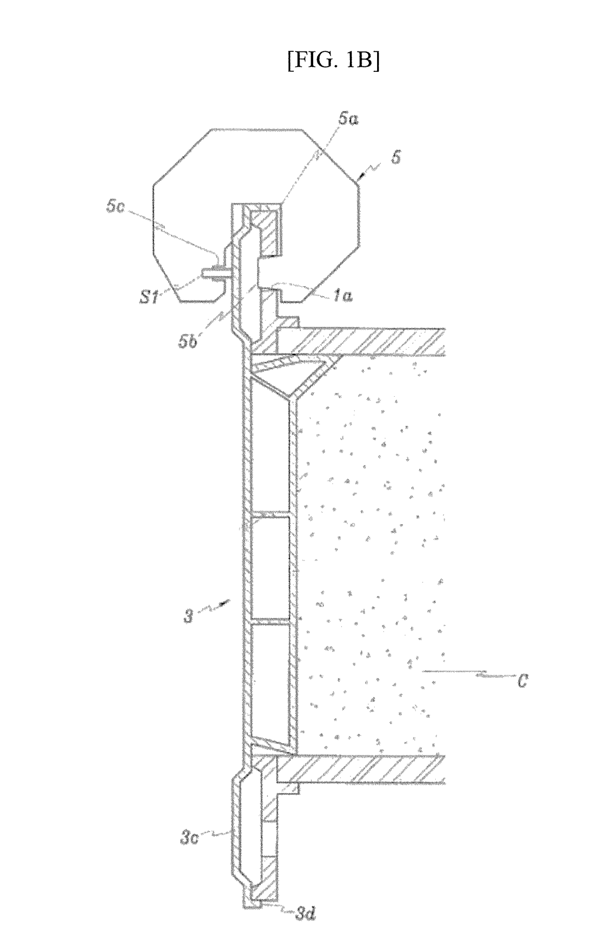
[0027]Exemplary embodiments of the present invention will be described in detail below with reference to the accompanying drawings. While the present invention is shown and described in connection with exemplary embodiments thereof, it should be apparent to those skilled in the art that various modifications can be made without departing from the spirit and scope of the invention.

[0028]Hereinafter, embodiments that are easily performed by those skilled in the art will be described in detail with reference to the accompanying drawings. However, embodiments of the present invention may be implemented in several different forms and are not limited to embodiments described herein. In addition, parts irrelevant to description are omitted in the drawings in order to clearly explain embodiments of the present invention. Similar parts are denoted by similar reference numerals throughout this specification.

[0029]Throughout this specification, when a certain part “includes” a certain componen...


PUM

PropertyMeasurementUnit
pressureaaaaaaaaaa
pouring pressureaaaaaaaaaa
shapeaaaaaaaaaa

Abstract

The present invention relates to a self-pouring mold system which ensures uniformity of a material by laterally pouring concrete into a mold installed on a side of a wall structure and minimizing a fall head generated when the concrete is poured to prevent bleeding, thereby ensuring uniformity of a fire-proofing material and adjusting a required fire-proofing coating thickness, and a method of fire-proofing, repairing, and reinforcing using the same.

Description

CROSS-REFERENCE TO RELATED APPLICATION[0001]This application claims priority to and the benefit of Korean Patent Application No. 2017-0017478, filed on Feb. 8, 2017, the disclosures of which are incorporated herein by reference in its entirety.BACKGROUND1. Field of the Invention[0002]The present invention relates to a self-pouring mold system and a method of fire-proofing, repairing, and reinforcing using the same and, more specifically, to a self-pouring mold system allows uniformity of a fire-proofing material to be ensured by pouring concrete at a side of a mold installed at a wall structure and minimizing a fall head generated when the concrete is poured to prevent bleeding and ensure uniformity of a material, and allows adjusting a fire-proof covering to be constructed in a required fire-proof thickness.2. Discussion of Related Art[0003]FIGS. 1A and 1B are installation views of an existing mold.[0004]Before a concrete wall C is built, molds are connected to a portion in which c...

Claims


Application Information

Patent Timeline
Patent Type & Authority Applications(United States)
IPC IPC(8): E21D11/10E04B1/94B28B7/18B28B23/00E04G11/06
CPCE21D11/107E04B1/944E04B1/948B28B7/186B28B23/005E04G11/06E04G17/045B29C33/42E04G9/10E04G11/08E04G11/085E04G17/002E04G21/04E21D11/10E04G21/0472E21D11/102E21D11/105B28B13/021
Inventor KIM, HEUNG YOULCHO, BUM YEON
Owner KOREA INST OF CIVIL ENG & BUILDING TECH
Why Eureka
Try Eureka