A clamp

a technology of clamping and spherical body, which is applied in the direction of couplings, pipe couplings, combustion air/fuel air treatment, etc., can solve the problems that the clamping does not provide, and achieve the effect of simple hole, robust alignment structure and convenient manufacturing of component ends

Active Publication Date: 2018-08-09
VOLVO LASTVAGNAR AB
View PDF0 Cites 1 Cited by
  • Summary
  • Abstract
  • Description
  • Claims
  • Application Information

AI Technical Summary

Benefits of technology

[0003]Clamps are widely used for connecting two open component ends to each other. One example is the so called V-band clamp, having two legs extending from a band, or web to form a V-shape. The ends of the web are provided with holes for receiving a bolt, and a nut is used to urge the two web ends towards each other. Hence the clamp forms a circular shape. While the clamp is not yet tightened it may be arranged around two flanges such that the legs of the clamp are arranged on each side of the flange connection. Upon tightening of the nut onto the bolt the diameter of the clamp will be reduced, thus providing a clamping effect to the flange connection.
[0024]In an embodiment the component ends are flanges. Preferably, one open end comprises at least one engagement structure, while the other open end comprises one or more engagement structures. This allows for an accurate clocking of the open ends relative each other, especially when one of the open ends has a fixed position. Further, this also allows for accurate clocking in different fixed positions.

Problems solved by technology

Hence, the clamp does not only provide clocking of the clamp relative the component ends, but also clocking of the component ends relative each other.

Method used


Image

  • A clamp
  • A clamp
  • A clamp

Examples


Embodiment Construction

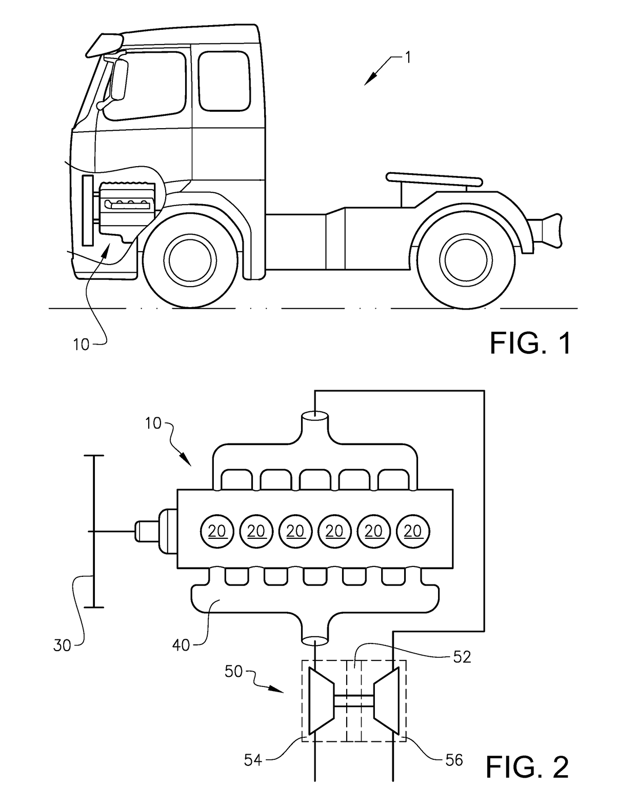
[0048]Starting with FIG. 1 a vehicle 1 is shown. The vehicle 1, which is illustrated as a truck, has an internal combustion engine 10 for driving the vehicle 1. As will be further explained below the internal combustion engine 10 of the vehicle 1 may be provided with various connections for joining two component ends to each other, e.g. connections of a turbocharger 50. Although the vehicle 1 is shown being a truck, it may also represent various vehicles such as buses, constructional equipment, etc.

[0049]In FIG. 2 an example of an internal combustion engine 10 is shown for which a clamp may be used. The internal combustion engine 10 includes a plurality of cylinders 20 operated to combust fuel, such as diesel or gasoline, whereby the motion of pistons reciprocating in the cylinders 20 is transmitted to a rotation movement of a crank shaft 30. The crank shaft 30 is further coupled to a transmission (not shown) for providing a torque to driving elements (not shown). In case of a heavy...


PUM


Abstract

A clamp for connecting a first component end to a second component end is provided. The clamp includes a web extending between a first end and a second end, each end being provided with a connecting device for connecting said web ends to each other so that the clamp encloses the component ends. The clamp further includes an alignment structure, which alignment structure is configured to fit with corresponding engagement structures provided at the first component end and the second component end for circumferentially positioning the clamp relative to the component ends.

Description

BACKGROUND AND SUMMARY[0001]The invention relates to a clamp for connecting a first component end to a second component end.[0002]The invention can be applied in a vast number of applications for which a clamping action is required to connect two component ends. One such application is when joining a compressor housing with a bearing housing of a turbocharger, and the clamp is thus particular useful for heavy-duty vehicles, such as trucks, buses and construction equipment. Although the invention will be described with respect to a truck, the invention is not restricted to this particular vehicle, but may also be used in other applications such as aero or marine systems, or any system for which two component ends are clamped together.[0003]Clamps are widely used for connecting two open component ends to each other. One example is the so called V-band clamp, having two legs extending from a band, or web to form a V-shape. The ends of the web are provided with holes for receiving a bol...

Claims


Application Information

Patent Timeline
Patent Type & Authority Applications(United States)
IPC IPC(8): F01D25/26F02C6/12F02M35/10F16L23/08F16L23/00
CPCF01D25/265F02C6/12F02M35/10144F16L23/08F16L23/003F05D2220/40F05D2260/30F05D2260/39F16L2201/60F02B37/00F01D25/24F16B2/08
Inventor ERIKSSON, PONTUS
Owner VOLVO LASTVAGNAR AB
Why Eureka
Try Eureka