Fuel injection controller and fuel injection control method for internal combustion engine

a fuel injection controller and internal combustion engine technology, applied in the direction of electric control, machines/engines, liquid fuel feeders, etc., can solve the problems of limiting the accuracy of the prediction of fuel pressure to the improvement of accuracy, and the corresponding error of the fuel injection amount. to achieve the effect of minimizing the error of the fuel injection amoun

Active Publication Date: 2018-08-16
TOYOTA JIDOSHA KK
View PDF0 Cites 9 Cited by
  • Summary
  • Abstract
  • Description
  • Claims
  • Application Information

AI Technical Summary

Benefits of technology

[0006]An objective of the present invention is to provide a fuel injection controller and fuel injection control method for an internal combustion engine capable of minimizing an error in a fuel injection amount.

Problems solved by technology

In such a case, there may occur an error in the fuel injection amount.
However, in the above conventional fuel injection controller, when there is an error in the predicted fuel pressure, there also occurs an error in the fuel injection amount corresponding to the error.
Thus, there is a limit determined by the accuracy of the prediction of fuel pressure to the improvement of the accuracy for the injection amount of the above conventional fuel injection controller.

Method used


Image

  • Fuel injection controller and fuel injection control method for internal combustion engine
  • Fuel injection controller and fuel injection control method for internal combustion engine
  • Fuel injection controller and fuel injection control method for internal combustion engine

Examples


first embodiment

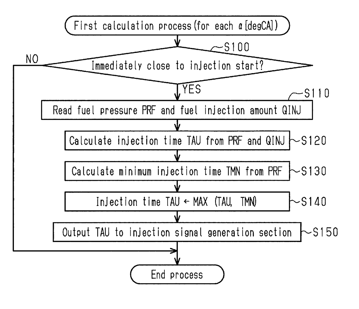
[0033]A fuel injection controller for an internal combustion engine according to a first embodiment will be described with reference to FIGS. 1 to 5.

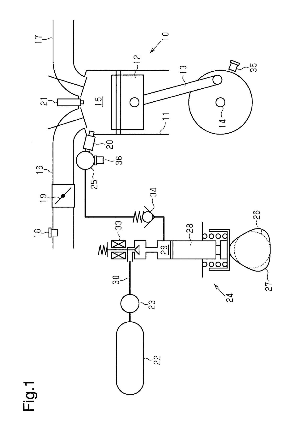
[0034]First, the configuration of an internal combustion engine 10 to which a fuel injection controller according to the present embodiment is applied will be described.

[0035]As illustrated in FIG. 1, the internal combustion engine 10 includes a cylinder 11 and a piston 12 arranged to reciprocate within the cylinder 11. The piston 12 is connected to a crankshaft 14, which is the output shaft of the internal combustion engine 10, via a connecting rod 13 configured to convert the reciprocating movement of the piston 12 into a rotating movement.

[0036]Inside the cylinder 11, a combustion chamber 15 is defined by the piston 12. To the combustion chamber 15, an intake passage 16 that is a passage for intake of air flowing into the combustion chamber 15 and an exhaust passage 17 that is a passage for exhaust of air discharged from the combusti...

second embodiment

[0073]Next, a second embodiment of the fuel injection controller will be described in detail with reference to FIGS. 6 and 7. In the present embodiment and each of the embodiments described later, configurations common to that described above are assigned the same reference numerals to omit detailed descriptions.

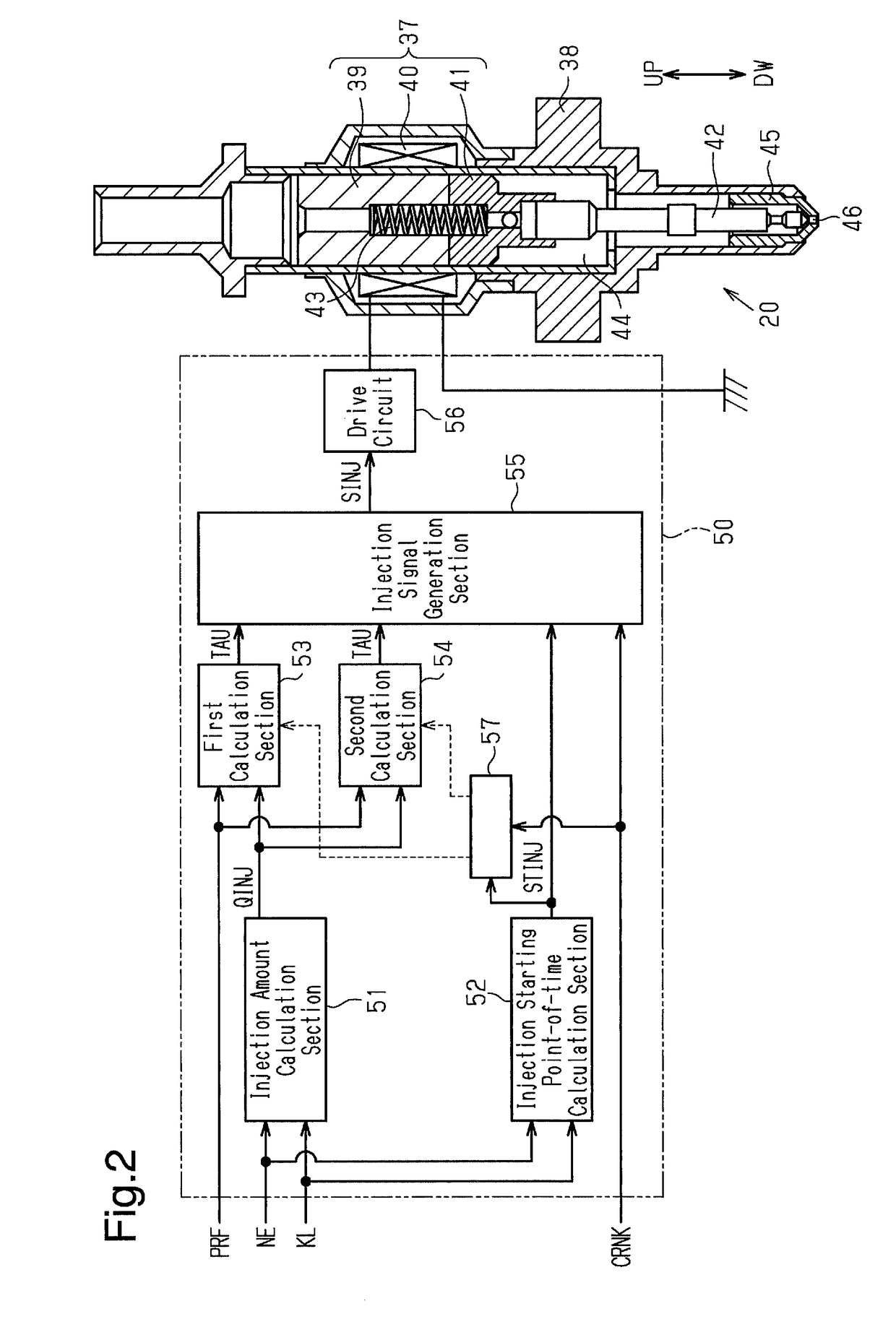
[0074]In the first embodiment, the calculation of the injection time TAU by the second calculation section 54 at the time of the start of the fuel injection is performed in substantially a similar way as in the calculation of the injection time TAU by the first calculation section 53. In order to ensure the accuracy for the injection amount, upon calculation of the injection time TAU, in addition to the fuel pressure PRF, a complicated calculation process is needed while taking into consideration factors such as individual differences in the injection characteristic of the injector 20 and the influence of the remaining magnetic force of the electromagnetic solenoid 37 from t...

third embodiment

[0084]Next, a third embodiment of the fuel injection controller will be described in detail with reference to FIGS. 8 and 9.

[0085]As described above, in the internal combustion engine 10 illustrated in FIG. 1, the fuel is supplied to the injector 20 through intermittent fuel feeding by the high-pressure fuel pump 24 according to the plunger 28 moving up and down. When the fuel feeding by the high-pressure fuel pump 24 described above is performed during the fuel injection by the injector 20, the fuel pressure PRF is changed, resulting in a change in the fuel injection amount.

[0086]FIG. 8 illustrates movements of the fuel pressure PRF when the fuel feeding is performed during the fuel injection with a solid line. FIG. 8 illustrates movements of the fuel pressure PRF when the fuel feeding is not performed with a long dashed short dashed line. In FIG. 8, during the period from a point of time t4 to a point of time t6, an injection signal is output and the fuel injection is implemented....


PUM


Abstract

A fuel injection controller for an internal combustion engine includes first and second calculation sections. The first calculation section acquires a fuel pressure at a predetermined point of time before an injection starting point of time and calculates an injection time using the acquired fuel pressure. The second calculation section acquires a fuel pressure when the injection starting point of time arrives and calculates the injection time by using the acquired fuel pressure. The controller is configured to, before starting the energization to the injector, set a point of time to stop energization to an injector based on a calculation result of the injection time by the first calculation section. The controller is also configured to, after starting the energization to the injector, reset the point of time to stop the energization to the injector based on a calculation result of the injection time by the second calculation section.

Description

BACKGROUND OF THE INVENTION[0001]The present invention relates to a fuel injection controller and a fuel injection control method for an internal combustion engine.[0002]In an internal combustion engine mounted on a vehicle, for example, a fuel injection control is performed in the following manner. The control involves calculating a fuel injection amount that is an amount of fuel to be injected from the injector and an injection starting point of time for starting the injection based on the operation state of an internal combustion engine (such as the speed and load of the internal combustion engine). Subsequently, the control involves calculating an injector energization time required for fuel injection of the calculated fuel injection amount as an injection time based on fuel pressure that is the pressure of fuel supplied to the injector. In the control, as a result of the energization being performed for the injection time from the injection starting point of time, the injector ...

Claims


Application Information

Patent Timeline
Patent Type & Authority Applications(United States)
IPC IPC(8): F02D41/40
CPCF02D41/40F02D2200/0602F02M37/043F02M51/061F02D41/04F02D41/345F02D2200/0614F02D2250/12F02D2250/14Y02T10/40
Inventor IMAI, SOHICHIIDOGAWA, MASANAO
Owner TOYOTA JIDOSHA KK
Why Eureka
Try Eureka