Decompression heat-insulating pipe structure

a heat-insulating pipe and compression technology, applied in the direction of heat treatment equipment, charge manipulation, furnaces, etc., can solve the problems of low resistance of elastic seal members, inability to use seal members at this temperature range or higher, and difficulty in using the structure of vacuum heat-insulating vessels

Active Publication Date: 2018-08-16
TOYOTA JIDOSHA KK
View PDF0 Cites 2 Cited by
  • Summary
  • Abstract
  • Description
  • Claims
  • Application Information

AI Technical Summary

Benefits of technology

[0014]According to the present disclosure, when the inner tube elongates axially due to the thermal expansion, the bellows is deformed elastically to elongate or contract and so absorbs a dimensional difference with the outer tube. In this way, sealing with the first seal member and with the second seal member can be kept.
[0015]The present disclosure can provide a decompression heat-insulating pipe structure that can be used in the system operating at high temperatures.

Problems solved by technology

When the structure of JP 2011-219125 A is used in the system so that the internal space of the inner tube is connected to a heating oven and is subjected to high temperature, the following problem may occur.
Therefore it is difficult to use the structure of the vacuum heat-insulating vessel of JP 2011-219125 A in the system operating at high temperatures.
The temperature that such an elastic seal member can be resistant to is low, and so these seal members cannot be used at this temperature range or higher.
On the contrary, seal members resistant to a higher temperature have low elasticity, and so cannot absorb the above dimensional difference with the elastic deformation.

Method used


Image

  • Decompression heat-insulating pipe structure
  • Decompression heat-insulating pipe structure
  • Decompression heat-insulating pipe structure

Examples


first embodiment

[0023]The following describes a first embodiment of the present disclosure in details, with reference to the drawings.

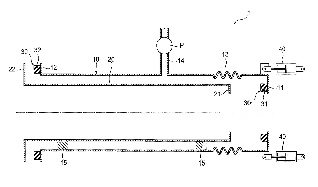
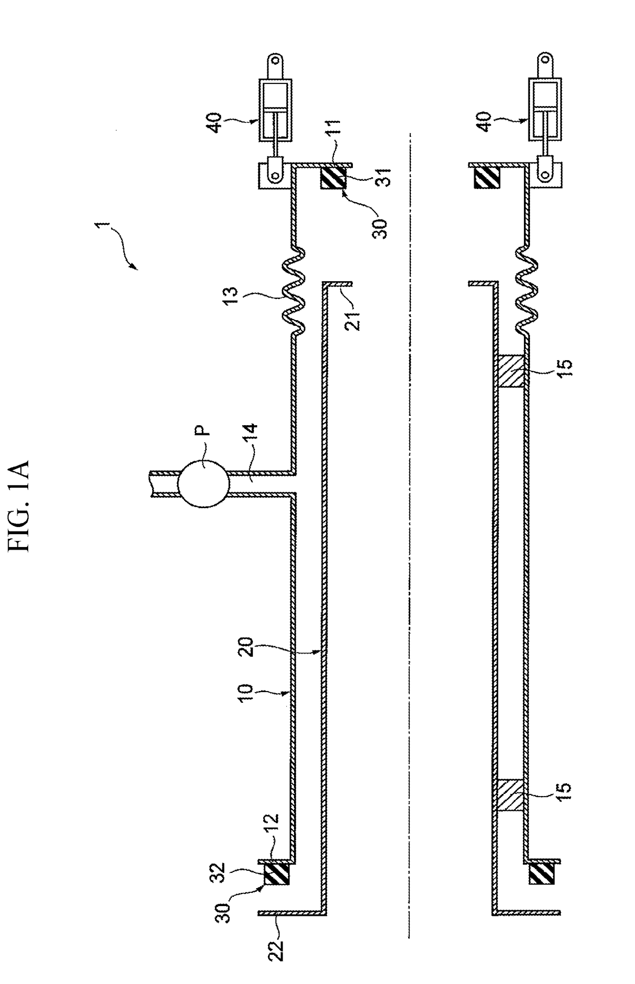
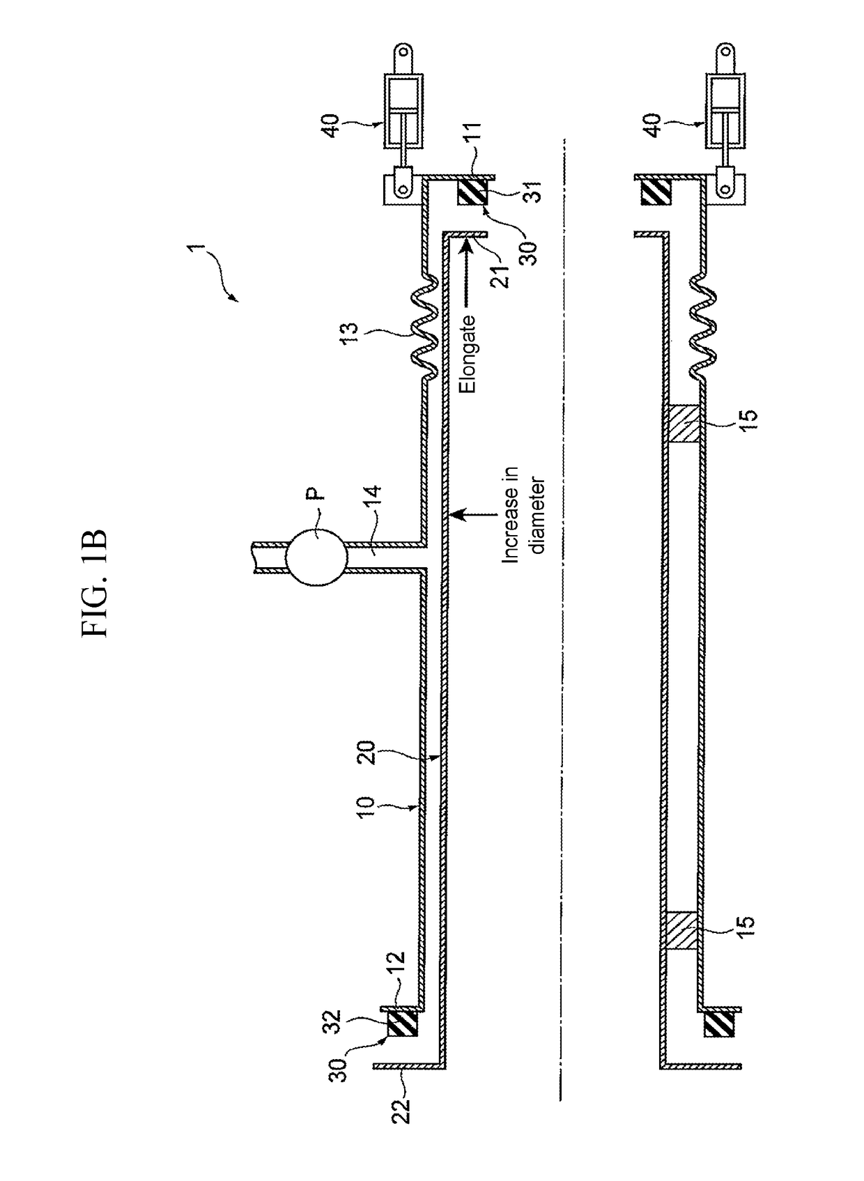
[0024]FIG. 1 schematically shows a heat-treating furnace in cross section, having a heat-insulating wall structure according to the first embodiment. FIG. 1A is a cross-sectional view showing the inner tube before thermal expansion, FIG. 1B is a cross-sectional view showing the inner tube that is thermally expanded, and FIG. 1C is a cross-sectional view of the decompressed space between the inner tube and the outer tube.

[0025]The heat-treating furnace 1 has a decompression heat-insulating pipe structure according to the present embodiment, and has a double-tube structure including an outer tube 10 and an inner tube 20 inserted into the outer tube 10.

[0026]The outer tube 10 and the inner tube 20 each have a cylindrical tubular shape having a constant diameter and extending in the axial direction. The outer tube 10 and the inner tube 20 are disposed on a base not illus...

second embodiment

[0052]The following describes a second embodiment of the present disclosure in details, with reference to the drawings.

[0053]FIG. 2 schematically shows a heat-treating furnace in cross section, having a decompression heat-insulating pipe structure according to the second embodiment. FIG. 2A is a cross-sectional view showing the inner tube before thermal expansion, FIG. 2B is a cross-sectional view showing the inner tube that is thermally expanded, and FIG. 2C is a cross-sectional view of the decompressed space between the inner tube and the outer tube.

[0054]The heat-treating furnace 2 has a double-tube structure with a bottom, including an outer tube 50 and an inner tube 60 inserted into the outer tube from the opening end. The outer tube 50 is a tubular member made of metal, such as stainless steel. The outer tube 50 has one end that is a closed end, and the other end that is an open end. Similarly to the outer tube 50, the inner tube 60 is a tubular member made of metal, such as s...


PUM

PropertyMeasurementUnit
heat resistanceaaaaaaaaaa
temperatureaaaaaaaaaa
heat resistanceaaaaaaaaaa

Abstract

Provided is a decompression heat-insulating pipe structure that can be used in the system operating at high temperatures. A decompression heat-insulating pipe structure of the present disclosure includes: an outer tube and an inner tube each having a flange; and a seal member between the flanges, the seal member being configured to keep a space between the outer tube and the inner tube in a decompression state, and a shifting means configured to shift the outer tube and the inner tube relatively so as to selectively dispose the tubes at a pressing position to press the seal member between the flanges and at a cancellation position to cancel the pressing of the seal member.

Description

CROSS REFERENCE TO RELATED APPLICATIONS[0001]The present application claims priority from Japanese patent application JP 2017-025898 filed on Feb. 15, 2017, the content of which is hereby incorporated by reference into this application.BACKGROUNDTechnical Field[0002]The present disclosure relates to a decompression heat-insulating pipe structure including a seal member between flanges of an outer tube and an inner tube, the seal member being configured to keep the space between the outer tube and the inner tube in a decompression state.Background Art[0003]JP 2011-219125 A discloses the structure of a vacuum heat-insulating vessel having a vacuum space between an outer tube and an inner tube. The outer tube and the inner tube of this vacuum heat-insulating vessel are joined by welding, for example, and so the vacuum insulating vessel has an integrated structure.SUMMARY[0004]When the structure of JP 2011-219125 A is used in the system so that the internal space of the inner tube is co...

Claims


Application Information

Patent Timeline
Patent Type & Authority Applications(United States)
IPC IPC(8): F16L59/065
CPCF16L59/065F16L51/02B01J10/005B01J12/005B01J19/0073C21D9/0006F16L59/143F16J15/061F16L9/18F16L27/11F16L27/12F16L51/025F27D3/0025F27D3/0033F27D3/18F27D99/0073
Inventor YAMASHITA, OSAMU
Owner TOYOTA JIDOSHA KK
Why Eureka
Try Eureka