Electric double-layer capacitor and method for manufacturing the same

a technology of double-layer capacitors and capacitors, which is applied in the direction of capacitors, multiple hybrid/edl capacitors, and electrolytic capacitors, can solve the problems and achieve the effect of low mechanical strength required for separators and increased mechanical strength of separators

Inactive Publication Date: 2018-08-16
MURATA MFG CO LTD
View PDF3 Cites 2 Cited by
  • Summary
  • Abstract
  • Description
  • Claims
  • Application Information

AI Technical Summary

Benefits of technology

[0009]In the electric double-layer capacitor according to the present invention, since the ratio of the intensity of the second peak to the intensity of the first peak is 0.08 or more, a mechanical strength of the separator is high. In the electric double-layer capacitor according to the present invention, the positive electrode and the negative electrode are arranged such that at least one set of edge sides corresponding to each other are in a different position in a plan view. For this reason, it is possible to suppress concentration of stress on specific portions of the separator. Therefore, the mechanical strength required for the separator is low. Accordingly, the separator can be thinned. Therefore, it is possible to reduce a thickness of the electric double-layer capacitor.
[0010]In the electric double-layer capacitor according to the present invention, it is preferred that the positive electrode and the negative electrode are arranged such that in a plan view, one set of edge sides corresponding to each other are in different positions, and the other set of edge sides corresponding to each other which are parallel to the one set of edge sides are in different positions. In this case, the mechanical strength required for the separator is lower. Therefore, the separator can be made thinner. As a result, it is possible to further reduce the thickness of the electric double-layer capacitor.
[0011]In the electric double-layer capacitor according to the present invention, it is preferred that the positive electrode and the negative electrode are arranged such that in a plan view, each set of edge sides corresponding to each other are in different positions. In this case, the mechanical strength required for the separator is further reduced. Therefore, the separator can be further thinned. As a result, it is possible to further reduce the thickness of the electric double-layer capacitor.
[0015]In the method for manufacturing an electric double-layer capacitor according to the present invention, the separator containing polyacrylonitrile is heated. Therefore, the mechanical strength of the separator can be increased. Further, the positive electrode, the heated separator, and the negative electrode are laminated such that edge side positions on at least the same one side of the positive electrode and the negative electrode are different from each other in a plan view. Therefore, when an external stress is applied to the produced electric double-layer capacitor, the stress hardly concentrates at a specific location of the separator. Therefore, the mechanical strength required for the separator is low. Therefore, the separator can be thinned. As a result, a thin electric double-layer capacitor can be manufactured.
[0016]According to the present invention, it is possible to provide a thin electric double-layer capacitor.

Problems solved by technology

Therefore, the mechanical strength required for the separator is low.

Method used


Image

  • Electric double-layer capacitor and method for manufacturing the same
  • Electric double-layer capacitor and method for manufacturing the same
  • Electric double-layer capacitor and method for manufacturing the same

Examples


first embodiment

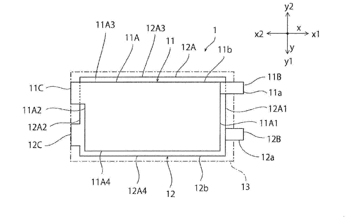
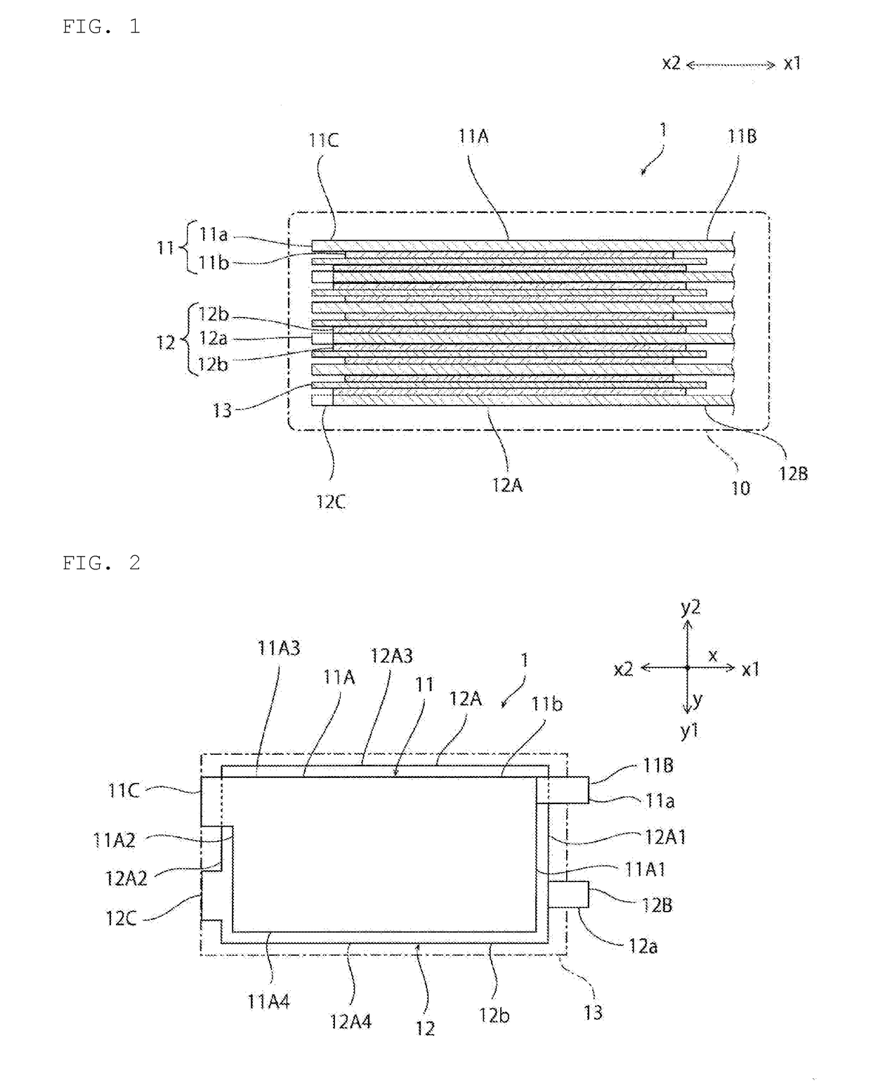
[0027]FIG. 1 is a schematic cross-sectional view of an electric double-layer capacitor according to the present embodiment. FIG. 2 is a schematic plan view of a main part of the electric double-layer capacitor according to the present embodiment. In FIG. 2, illustration of an outer case 10 is omitted.

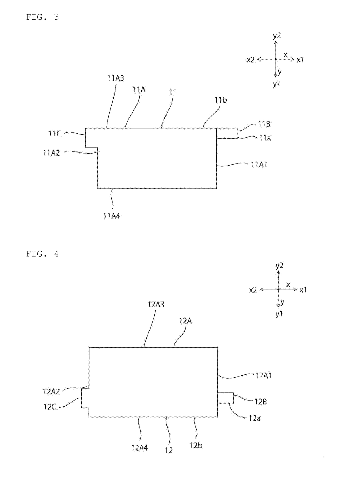
[0028]As shown in FIG. 1, the electric double-layer capacitor 1 has a first electrode 11, a second electrode 12, a separator 13, and an outer case 10.

[0029]The first electrode 11 and the second electrode 12 are opposed to each other with the separator 13 interposed therebetween. Specifically, a plurality of first electrodes 11 and a plurality of second electrodes 12 are alternately laminated with the separator 13 interposed therebetween. The first electrodes 11 are electrically connected to each other by a first extended terminal (not shown), and is extended to the outside of the outer case 10. The second electrodes 12 are electrically connected to each other by a second extended termin...

second embodiment

[0076]FIG. 5 is a schematic plan view of an electric double-layer capacitor 1a according to the present embodiment.

[0077]In the present embodiment, the electric double-layer capacitor 1a includes a first electric double-layer capacitor element 31a enclosed in a package 31c and a second electric double-layer capacitor element 31b. Each of the first and second electric double-layer capacitor elements 31a and 31b has a rectangular shape whose longitudinal direction is parallel to the x-axis direction (second direction). The first electric double-layer capacitor element 31a and the second electric double-layer capacitor element 31b are arranged along the x-axis direction. Therefore, the package 31c also has a rectangular shape whose longitudinal direction is parallel to the x-axis direction.

[0078]The package 31c is provided with a rectangular first cell 31c1 and a rectangular second cell 31c2 adjacent to the first cell 31c1 in the x-axis direction. A first electric double-layer capacito...

example 1

[0118]A nonwoven fabric of polyacrylonitrile having a thickness of 17 μm and an average fiber diameter of 0.3 and formed of a polyacrylonitrile homopolymer was heated at 230° C. for 72 seconds in an oxidizing atmosphere, and used as a separator. Using the resulting separator, an electric double-layer capacitor having substantially the same configuration as the electric double-layer capacitor 1 according to the first embodiment was fabricated.


PUM


Abstract

An electric double-layer capacitor having a separator that contains polyacrylonitrile. An infrared absorption spectrum of the separator measured by a Fourier transform infrared spectrophotometer has a first peak in a range from 2240 cm−1 to 2250 cm−1 and a second peak in a range from 1580 cm−1 to 1630 cm−1. A ratio of an intensity of the second peak to an intensity of the first peak is 0.08 or more.

Description

CROSS REFERENCE TO RELATED APPLICATIONS[0001]The present application is a continuation of International application No. PCT / JP2016 / 080155, filed Oct. 11, 2016, which claims priority to Japanese Patent Application No. 2015-216414, filed Nov. 4, 2015, the entire contents of each of which are incorporated herein by reference.FIELD OF THE INVENTION[0002]The present invention relates to an electric double-layer capacitor and a method for manufacturing the electric double-layer capacitor.BACKGROUND OF THE INVENTION[0003]Conventionally, capacitors are widely used in various electronic devices such as mobile phones. An electric double-layer capacitor (EDLC) is known as a capacitor. Since the electric double-layer capacitor does not involve a chemical reaction in charging and discharging, unlike the secondary battery, it has an advantage of having a long product life and an advantage that a large current can be charged and discharged in a short time. Accordingly, attempts have been made to a...

Claims


Application Information

Patent Timeline
Patent Type & Authority Applications(United States)
IPC IPC(8): H01G11/52H01G11/22H01G11/86H01G11/58H01G11/66
CPCH01G11/52H01G11/22H01G11/86H01G11/58H01G11/66H01G11/04H01G11/12H01G11/28H01G11/84Y02E60/13
Inventor HORIKAWA, KEIJI
Owner MURATA MFG CO LTD
Why Eureka
Try Eureka