High torsion delivery catheter element

a catheter element and high torsion technology, applied in the field of high torsion delivery catheter elements, can solve the problems of affecting the operation of the medical implant devi

a catheter element and high torsion technology, applied in the field of high torsion delivery catheter elements, can solve the problems of affecting the operation of the medical implant devi

US20180235657A1Active Publication Date: 2018-08-23ABBOTT CARDIOVASCULAR

Image

  • High torsion delivery catheter element
  • High torsion delivery catheter element
  • High torsion delivery catheter element

Examples


Embodiment Construction

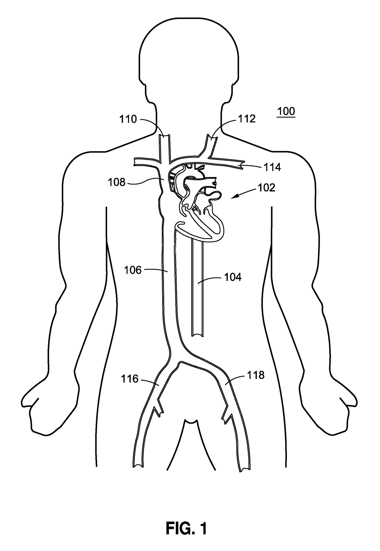
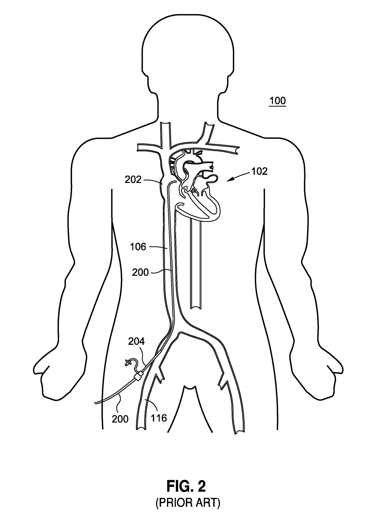
[0025]As may be understood from this detailed description, as read in conjunction with the figures, a delivery system for transcatheter delivery, having features of the invention, is described. The context of the invention is explained above with initial reference to FIGS. 1-3.

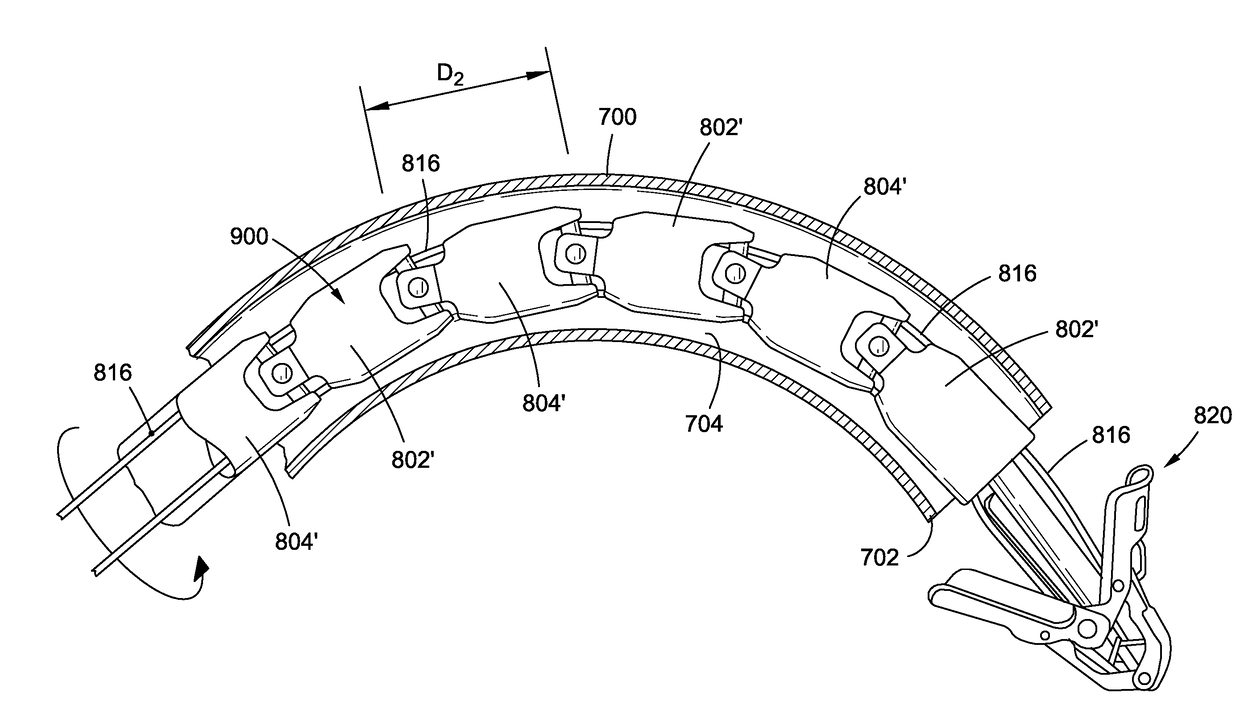
[0026]With reference now to FIGS. 4-11, in some embodiments the invention includes a jointed system 800 for a delivery element suitable for use in delivering medical repair devices. In a preferred embodiment, the invention includes a first cylindrical segment 802 which is hollow, having a central bore 803 and a second cylindrical segment 804 which is hollow, having a central bore 805. Each of these cylindrical segments may be made from a metal or from a polymer, and may be cut from a parent cylinder using known micro-cutting means such as laser energy and micro-drilling. In other cases cylindrical segments may be constructed of braided or composite shafts or polymer extrusions with any number of internal lumen...


PUM


Abstract

A jointed system for delivering a medical device to a target location within a human anatomy, comprising: a first segment that is a hollow cylinder, wherein a first flange and a second flange are attached to the distal end and extend distally away from the first segment; a second segment that is a hollow cylinder and has a proximal end and a distal end, wherein a third flange and a fourth flange are attached to the proximal end and extend proximally away from the second segment; a connector element having four cylindrical lugs extending radially away from a central point, wherein each lug passes, respectively, through a circular hole, and further wherein the connector element defines at least two separate openings extending in a direction from the distal end of the first segment to the proximal end of the second segment.

Description

BACKGROUND[0001]This application relates to systems and methods for implanting devices such as replacement heart valves, valve repair devices such as clips, stents, and similar therapeutic devices within the anatomy of a patient.[0002]It is well known in the art to implant devices such as replacement heart valves, valve repairing clips, stents, reinforcement rings, and the like into the human heart to restore its function. Similar devices are also introduced into other parts of the human anatomy where mechanical repair is needed. Many such repair operations are carried out by first inserting a steerable delivery catheter by minimally invasive means into a desired organ of the human anatomy. Thereafter, a repair device positioned on the distal tip of a delivery element is passed through an internal lumen along the entire length of the delivery catheter until the repair device reaches the target organ, and the device is pushed out of the distal end of the catheter for implantation. Su...

Claims


Application Information

Patent Timeline
23 Aug 2018
Publication
US20180235657A1
IPC
A61B17/34; A61M25/00
CPC
A61M25/0054; A61B17/3468; A61B1/008; A61F2/2466; A61M25/0138; A61B2017/00314
Inventors
ABUNASSAR, CHAD