Easily retrievable implant-abutment device

a technology of implant abutment and easy-to-retrieve, which is applied in the field of easy-to-retrieve implant abutment devices, can solve the problems of difficult to produce integral-type implants, limited use of implants, and like may be released or broken, so as to improve economic efficiency, facilitate the retrieval of implant abutments, and save components

Inactive Publication Date: 2018-08-23
ACRODENT
View PDF5 Cites 6 Cited by
  • Summary
  • Abstract
  • Description
  • Claims
  • Application Information

AI Technical Summary

Benefits of technology

[0030]According to embodiments of the present disclosure, provided is an easily retrievable implant-abutment device that is not only capable of maintaining a coupled position in a state where an abutment is coupled to a fixture, but also capable of allowing a slight movement under a predetermined external force(that is to say when a force, lower than a predetermined external force, is exerted) occurring due to an occlusal force of occluding teeth, and further in which, as necessary, the abutment is able to be separated from the fixture when an external force that is equal to or greater than a target coupling force for maintaining a coupled state therebetween is exerted.
[0031]Further, it is advantageously possible to provi...

Problems solved by technology

However, bacteria may be propagated around a coupled portion, or coupling means such as a screw, and the like may be released or broken.
However, the integral-type implant requires a long procedure time such that it causes inconvenience.
Further, it may be difficult to produce the integral-type implant in consideration of various diameters lengths, and angles, all of which are individually required by users.
Accordingly, the use thereof may be limited.
However, when accurately coupled to each other, the abutment and the fixture may be hastily separated from each other.
However, in the case of this conventional technology, an elastic body is pro...

Method used


Image

  • Easily retrievable implant-abutment device
  • Easily retrievable implant-abutment device
  • Easily retrievable implant-abutment device

Examples


first exemplary embodiment

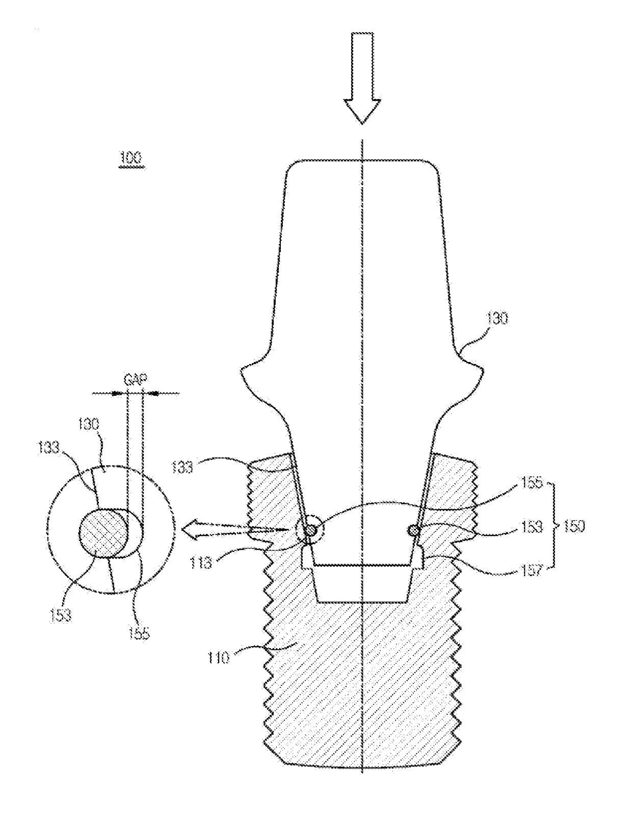
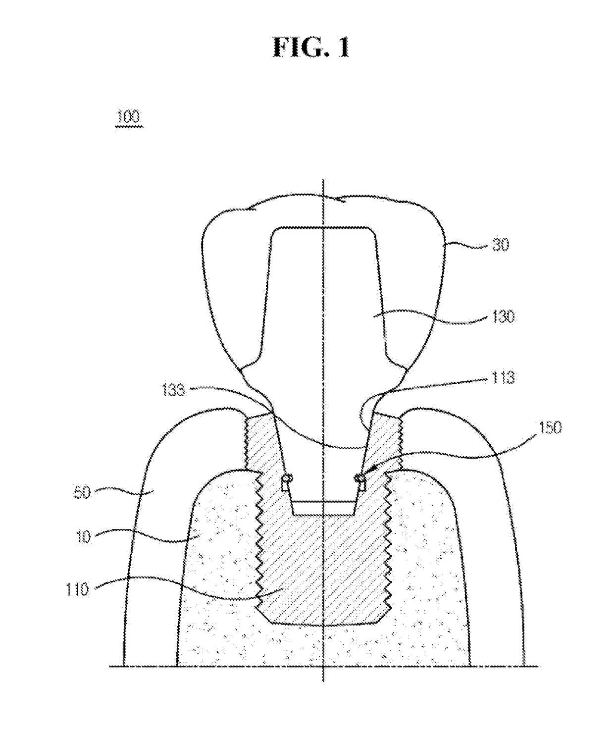
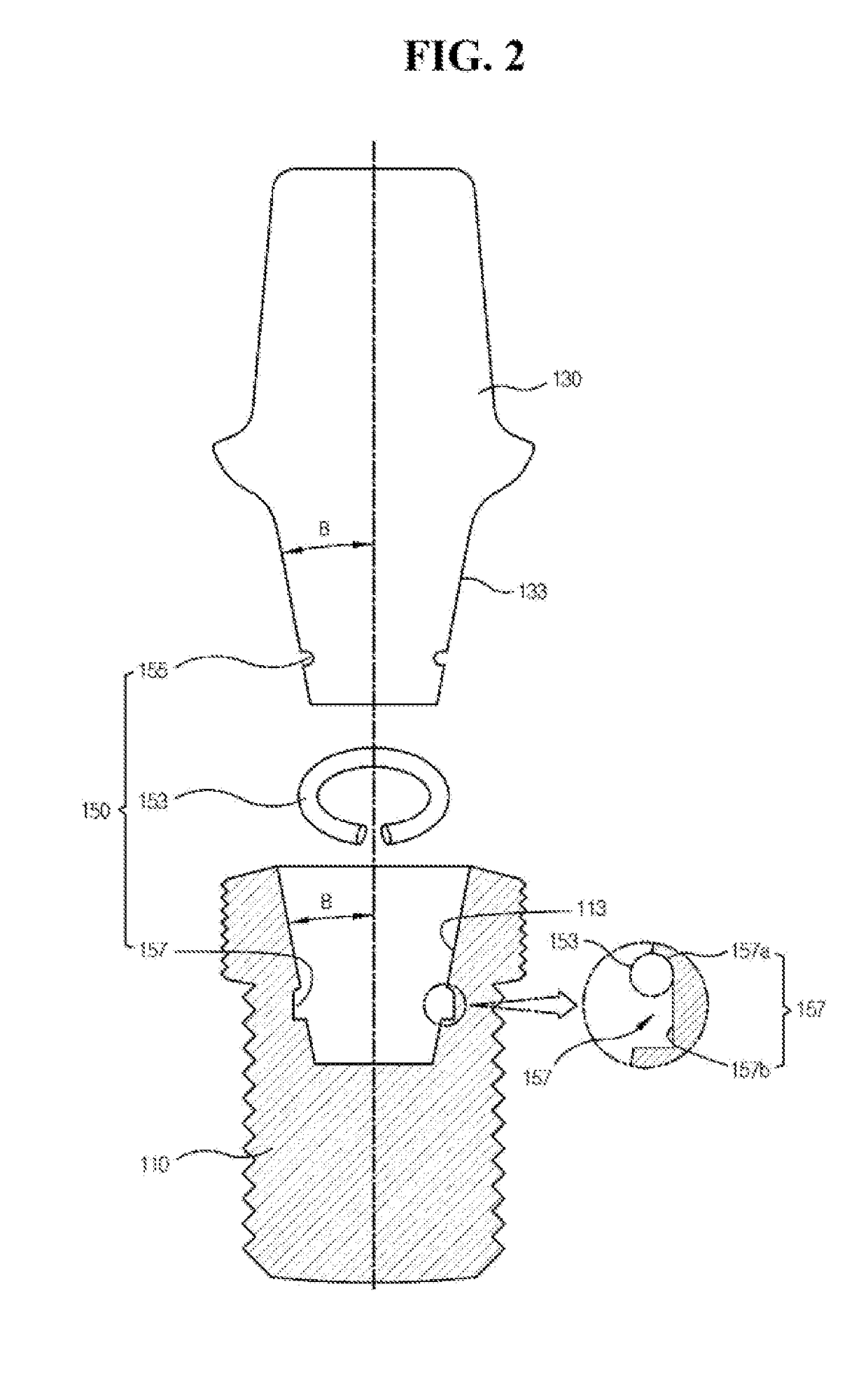
[0053]As shown in FIG. 1, an implant including the implant device 100 includes a fixture 110 that is coupled to an alveolar bone 10 and includes a female tapered part 113 having a tapered shape w aa inner side thereof; a gum 50 that is exposed, outwards from an upper side of the alveolar bone 10; an abutment 130 that is coupled to the fixture 110; and a dental prosthesis 30 or a crown that Is coupled to the abutment 130 and then forms an outer shape, and has occlusion with occluding teeth, that is to say has contact between the occluding teeth.

[0054]One side of the abutment 130 includes a male tapered part 133, a shape of which corresponds to the female tapered part 113 so as to be interlocked and coupled to the female tapered part 113, and the other side thereof is coupled to the dental prosthesis 30.

[0055]An elastic part 150 is provided between the female tapered part 113 and the male tapered part 133 so as for the abutment 130 to be movable between a locking position (refer to FI...

second exemplary embodiment

[0076]An implant device 200 according to another exemplary embodiment will now be described in detail with reference to FIG. 4. Additionally, reference numerals in one digit and two digits described hereinafter will be the same as those of the first exemplary embodiment describe hereinabove.

[0077]Contrary to the exemplary embodiment described above, an elastic member coupling groove 255 according to a second exemplary embodiment, to which an elastic member 253 is elastically and deformably coupled, is formed in a fixture 210, and an elastic member groove 257, in which the elastic member 253 is movable such that an sinking effect may occur, is formed in an abutment 230. In other words, the elastic member 253 is configured to be adhered to an inner diameter of the elastic member groove 257 at a locking position.

[0078]Functions, effects, actions, and the like of respective configurations except the configurations and positions described above in the second exemplary embodiment are the ...

third exemplary embodiment

[0079]As shown in FIG. 5, an implant device 300 according to a third exemplary embodiment further includes rotation preventing parts 115 and 135 having hexagonal cross sections that are formed in portions where a female tapered part 313 and a male tapered part 333 are provided or in portions extended from the portions where the female tapered part 313 and the male tapered part 333 are provided so as to inhibit up-and-down rotation in a state where an abutment is coupled to a fixture, and an elastic part 350 is formed in the rotation preventing parts 115 and 135. Functions, effects, actions, and the like of respective configurations except the rotation preventing parts 115 and 135, and the elastic part 350 in the third exemplary embodiment are the same as those in the exemplary embodiments described hereinabove, so detailed descriptions thereof will be omitted.

[0080]As described above, the rotation preventing parts 115 and 135 may be also formed in the female tapered part 313 and the...


PUM


Abstract

The present invention relates to an implant-abutment comprising: a fixture, which is coupled to an alveolar bone and comprises on the inside thereof a female tapered part having a tapered shape; an abutment, which has one side comprising a male tapered part, which has a shape corresponding to the female tapered part so as to be coupled to the female tapered part in an engaging manner, and the other side having a prosthesis coupled thereto; and an elastic part provided between the female tapered part, and the male tapered part so as for the abutment to move between a locking position, in which the abutment stays coupled to the fixture and is inhibited from moving away from the alveolar bone, and a sinking position, in which the abutment moves and sinks toward the alveolar bone by the occlusal force of occluding teeth. Configured as such, the present invention allows slight movement under a predetermined external, force by the occlusal force of teeth while stably maintaining the state of being coupled to the fixture and allows the abutment to be separated and easily retrieved from the fixture, if necessary, by the application of an external force equal to or greater than a target coupling force whereby the fixture and abutment stay coupled.

Description

BACKGROUND OF THE DISCLOSURE1. Field of the Disclosure[0001]The present disclosure relates to air easily retrievable implant-abutment device, and more particularly, to an easily retrievable implant-abutment device that is not only capable of maintaining a coupled position in a state where an abutment is coupled to a fixture, but also capable of retrievably coupling the abutment into the fixture.2. Description of the Related Art[0002]Recently, an implant surgery procedure for replacing damaged teeth or missing teeth has been generalized. Such an implant surgery method performs a series of processes in which an alveolar bone is drilled and a fixture is implanted into the alveolar bone, after which an abutment is coupled to the fixture and lastly a dental prosthesis is fixed to the abutment[0003]Provided are widely well-known method in which the abutment is coupled to the fixture as follows: a coupling type in which the abutment is coupled to the fixture by a screw, and the like as a f...

Claims


Application Information

Patent Timeline
IPC IPC(8): A61C8/00
CPCA61C8/0042A61C8/0012A61C2008/0046A61C8/0086A61C8/0057A61C8/0062A61C8/0069
Inventor LEE, JUN HO
Owner ACRODENT
Why Eureka
Try Eureka