Portable, Compact and Automated Cage Making Machine

a cage making machine and compact technology, applied in the direction of wire networks, structural elements, building components, etc., can solve the problems of high production costs, material wastage during production process, and the manual production of cages affecting the torsion of bars, so as to prevent the wasting of tensional resistance of bars, improve quality and strength, and improve the effect of quality

Active Publication Date: 2018-08-23
DAVOODI OMID +2
View PDF7 Cites 7 Cited by
  • Summary
  • Abstract
  • Description
  • Claims
  • Application Information

AI Technical Summary

Benefits of technology

[0009]Spot welding of bars and stirrups is done under the consideration of technical criteria and relevant standards, so this considerations cause higher strength and prevent wasting tensional resistance of bars, so the application of this welding method leads to higher quality and strength and the joints will be identical in comparison with traditional methods.
[0010]These properties together with continuity and regularity of stirrups of the cages produced by invented system, increases the quality of cages, which accordingly gain the strength of cages against pressures and forces applied to pillars, piles, beams and reinforcing cages. Furthermore, material wastage (stirrup or steel bar) will be eliminated during the producing steps.

Problems solved by technology

Reinforcing cages are formed by connecting shaped stirrups around longitudinal bars, which is usually done in traditional manner by labor and considered as time consuming and intolerable activities and required lots of preparation before manufacturing the cages.
Furthermore, employing large number of workers who involve making cages in long period, results higher production costs.
Moreover, manual producing of cages affected bars with torsion and to some extent bending and the stirrups do not connect to bars firmly and regularly.
Material wastages during production process can be considered as another difficulty.
These machines don't have the necessary adaptability in compassion with manual making of reinforcing cages with different shapes and dimensions and various size of re-bars and stirrups, at all.
Moreover high weight and massive dimension of these machines cause difficult transportation of them.
Transporting of the cages, may results problems and excess costs in conjunction with quality reduction of joints and even deformation of cage configuration and its elements.
Since aforesaid difficulties of these machines exist, utilizing the manual methods is still common in many of construction projects.

Method used


Image

  • Portable, Compact and Automated Cage Making Machine
  • Portable, Compact and Automated Cage Making Machine
  • Portable, Compact and Automated Cage Making Machine

Examples


Embodiment Construction

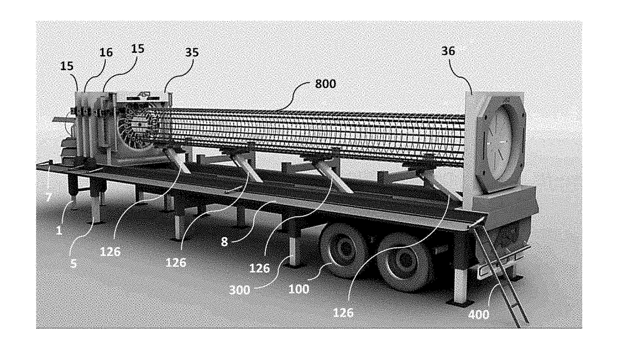
[0039]FIG. 1 shows the invented machine mounted on a flat trailer (100) in resting mode. In this case, trailer (100) containing invented machine, can be transported by a crawler (200) to a particular construction jobsite, for fabricating the reinforcing cage. After bringing the crawler to jobsite, the hydraulic cylinders (300) of trailer will be opened and the crawler (200) can be separated from the trailer. Then central hydraulic system of the machine commands to activate stands (1) which are two hydraulic cylinders connected to frame (2) by a pivot joint.

[0040]Therefore these stands will be opened after a 90 degrees rotation and the frame (2), where the winch (3) is mounted on; changes its position from vertical to horizontal by a pivot joint (frame (2) can be moved by hydraulic cylinder (4), as can be seen in FIG. 2). Therefore, the stands (1) with the aid of its hydraulic cylinders lay on the ground. Two stands (5) which are hydraulic cylinders pivoted to main chassis (6), are a...


PUM


Abstract

The invention is an automated machine for reinforcement of piles, pillars, beams, and reinforcing cages in location of construction projects. This machine consists of main elements like loading arms and feeding jaws of longitudinal bars, rotating winch for stirrup and its guides, fixed and moving jaws and welding robot. It can be installed on a specified flat trailer in resting mode and come to an operative mode in project location and will be ready to use. To make reinforcing cages, an automated method for continuous winding of stirrup around longitudinal bars has been applied, and two intelligent welding systems (resistive spot and CO2 welding methods) have been utilized for joints in this machine.

Description

FIELD OF THE INVENTION[0001]This machine has been invented to produce reinforcing cages automatically in construction projects. In other words, this portable and compact machine has been specifically invented to wind stirrup around rebar, automatically.BACKGROUND OF THE INVENTION[0002]Reinforcing cages are formed by connecting shaped stirrups around longitudinal bars, which is usually done in traditional manner by labor and considered as time consuming and intolerable activities and required lots of preparation before manufacturing the cages. Furthermore, employing large number of workers who involve making cages in long period, results higher production costs. Moreover, manual producing of cages affected bars with torsion and to some extent bending and the stirrups do not connect to bars firmly and regularly.[0003]Material wastages during production process can be considered as another difficulty. To solve the problems of manual production; many huge machines have been invented for...

Claims


Application Information

Patent Timeline
Patent Type & Authority Applications(United States)
IPC IPC(8): B21F27/12E04C5/06
CPCE04C5/0622B21F27/122E04C5/0618
Inventor DAVOODI, OMIDGHOLAMI, AHMADZAMANI, ELHAM
Owner DAVOODI OMID
Why Eureka
Try Eureka