Lubrication structure for internal combustion engine

a technology for internal combustion engines and lubrication structures, which is applied in the direction of machines/engines, lubrication elements, pressure lubrication, etc., can solve the problems of increasing the weight and cost of the engine, increasing the number of assembly steps, and increasing the number of components. , to achieve the effect of enhancing the cooling performance of the piston, simplifying the oil passage, and reducing the number of components

Active Publication Date: 2018-08-23
SUZUKI MOTOR CORP
View PDF0 Cites 3 Cited by
  • Summary
  • Abstract
  • Description
  • Claims
  • Application Information

AI Technical Summary

Benefits of technology

[0006]In the light of the aforementioned circumstances, an object of the present invention is to provide a lubrication structure for an internal combustion engine that can reduce a number of components and the like by simplifying an oil passage for feeding oil to a piston jet, and enhance piston cooling performance.
[0008]According to the present invention, an oil communication passage branches from an oil supply passage, and is provided across a lower crankcase and an upper crankcase, and therefore can be simplified without having a complicated shape. The oil communication passage is not configured by a separate component from a crankcase, so that the number of components and the like can be reduced. Oil from a main gallery is guided to the piston jet through the oil supply passage, the oil communication passage and a sub gallery in the state where pressure of the oil is ensured. Consequently, piston cooling performance can be enhanced by the oil that is injected from the piston jet.

Problems solved by technology

Moreover, disposition of an oil passage for supplying oil to the piston jet is also difficult, and it is also necessary to ensure oil pressure for injecting oil from the piston jet.
When the oil passage for supplying oil to the piston jet is complicated, the number of machining steps of the oil passage increases.
Further, when oil is supplied to the piston jet (the injection nozzle) by using the oil passages (the oil conduit and the oil distribution pipe) externally attached to the engine as described in Patent Document 1, the number of components, the number of assembly steps, and the weight and cost of the engine increase.
Further, there is a fear of oil leakage in the oil passage externally attached.

Method used


Image

  • Lubrication structure for internal combustion engine
  • Lubrication structure for internal combustion engine
  • Lubrication structure for internal combustion engine

Examples


Embodiment Construction

[0020]Hereinafter, embodiments for carrying out the present invention will be described based on drawings.

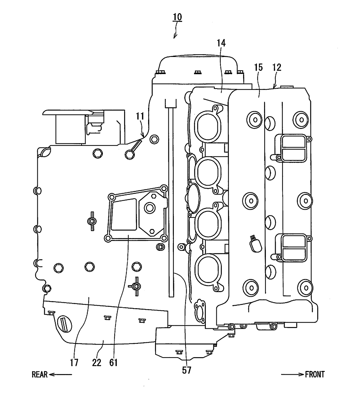
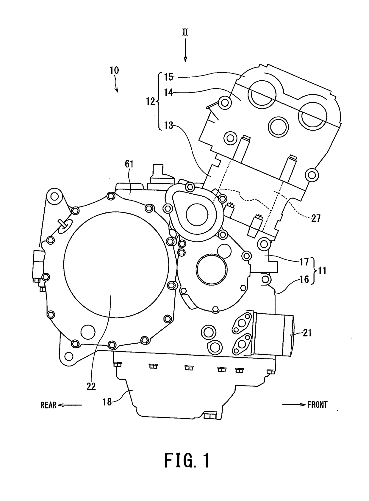
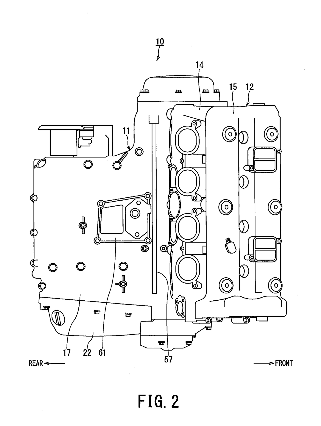
[0021]FIG. 1 is a right side view illustrating an engine to which an embodiment of a lubrication structure for an internal combustion engine according to the present invention is applied. FIG. 2 is a view seen from arrow II in FIG. 1. An engine 10 as the internal combustion engine illustrated in FIGS. 1 and 2 is to be loaded on a motorcycle, for example, and a cylinder assembly 12 is connected to a crankcase 11 by being tilted forward.

[0022]The cylinder assembly 12 is configured by a cylinder block 13, a cylinder head 14 and a head cover 15 being sequentially connected from below. By combustion of mixture gas that is supplied to a combustion chamber (not illustrated) in the cylinder head 14, a piston 27 reciprocates in the cylinder block 13, and the reciprocation rotates a crankshaft 23 (FIG. 3) via a connecting rod not illustrated.

[0023]As is also illustrated in FIG. 3, the cra...


PUM


Abstract

A lubrication structure for an internal combustion engine includes an oil pump, a main gallery, an oil-supply passage, a sub gallery, and an oil-communication passage. The oil pump is installed in a crankcase configured by connecting an upper crankcase on a mating surface of a lower crankcase from above. The main gallery is provided in the lower crankcase for supplying oil from the oil pump to the engine. The oil-supply passage is provided in the lower crankcase and supplies oil from the main gallery to a mating-surface-oil passage of the mating surface. The sub gallery is provided in the upper crankcase for guiding oil to a piston jet that injects oil toward a piston of the engine. The oil-communication passage is provided across the lower and upper crankcases, branches from the oil-supply passage to communicate with the sub gallery, and guides oil in the oil-supply passage to the sub gallery.

Description

CROSS-REFERENCE TO RELATED APPLICATIONS[0001]This application claims the benefit of priority of Japanese Patent Application No. 2017-027793, filed on Feb. 17, 2017, the entire contents of which are incorporated herein by reference.BACKGROUND OF THE INVENTIONField of the Invention[0002]The present invention relates to a lubrication structure for an internal combustion engine that supplies oil to a piston jet for cooling a piston of an internal combustion engine.Description of the Related Art[0003]The thermal load on a piston increases with increase in an output power of an engine, so that importance of a piston jet that cools a piston by injecting oil to a back surface of the piston is increasing. A piston reciprocates in a cylinder block, and a connecting rod draws a large trajectory in response to this, so that disposition of the piston jet that injects oil to the back surface of the piston is limited to a very narrow range.[0004]Moreover, disposition of an oil passage for supplyin...

Claims


Application Information

Patent Timeline
Patent Type & Authority Applications(United States)
IPC IPC(8): F01M1/08F01M11/02F01M1/02F01M1/04
CPCF01M1/08F01M1/02F01M1/04F01M11/02
Inventor MORI, MASAKI
Owner SUZUKI MOTOR CORP
Why Eureka
Try Eureka