
Friction damper

a damper and friction technology, applied in the field of friction dampers, can solve the problems of increasing the rigidity of the elastic body, the risk of radial vibration of the inner and outer shafts, etc., and achieve the effects of reducing the risk of deterioration of the coaxial centering function, and increasing the rigidity of the area

Active Publication Date: 2018-08-23
TOYOTA JIDOSHA KK
View PDF3 Cites 6 Cited by
  • Summary
  • Abstract
  • Description
  • Claims
  • Application Information

AI Technical Summary

Benefits of technology

The invention relates to a friction damper used in power transmitting systems of vehicles. The technical effects of the invention include reducing the risk of tooth butting noise and deterioration of the coaxial centering function of the spline-fitting portion, which is performed without separation of the teeth of the inner and outer shafts during transmission of rotary motion. The friction damper achieves this by increasing the rigidity of the elastic body in its circumferential direction and restricting the increase of rigidity in its radial direction. This allows for a sufficient degree of friction resistance in the spline-fitting portion to perform its function without separation of teeth. Additionally, the friction damper can be easily installed in the annular space between the inner and outer shafts of the vehicle power transmitting system.

Problems solved by technology

However, a mere increase of the wall thickness of the elastic body results in an increase of the rigidity of the elastic body in the radial direction between the inner and outer shafts.
The increase of the rigidity of the elastic body in the radial direction between the inner and outer shafts reduces an amount of relative radial displacement of the inner and outer shafts, and causes deterioration of an automatic coaxial centering function to be performed without separation of teeth of the spline-fitting portion away from each other during transmission of a rotary motion between the inner and outer shafts, giving rise to a risk of generation of radial vibrations of the inner and outer shafts due to their concentric misalignment, which radial vibrations have a frequency corresponding to a multiple of rotating speed of the inner and outer shafts.

Method used


Image

  • Friction damper
  • Friction damper
  • Friction damper

Examples


first embodiment

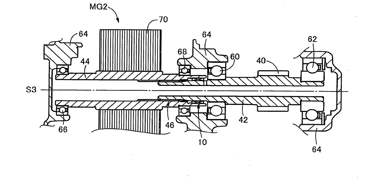
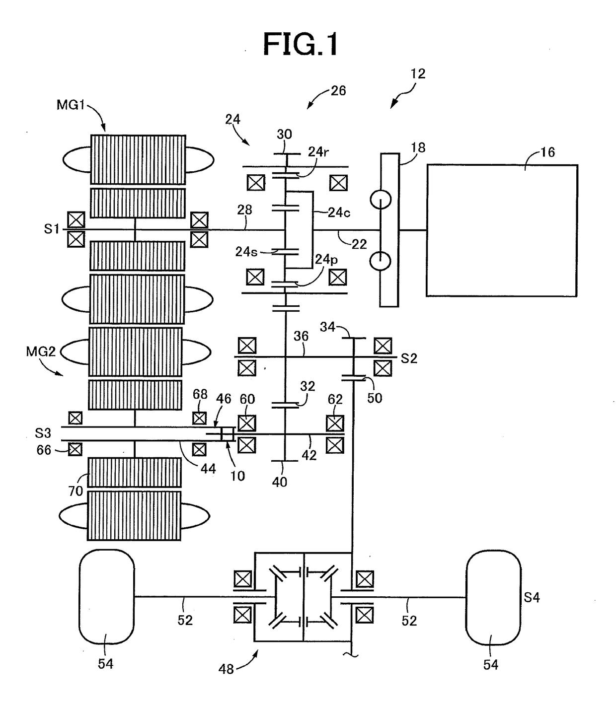
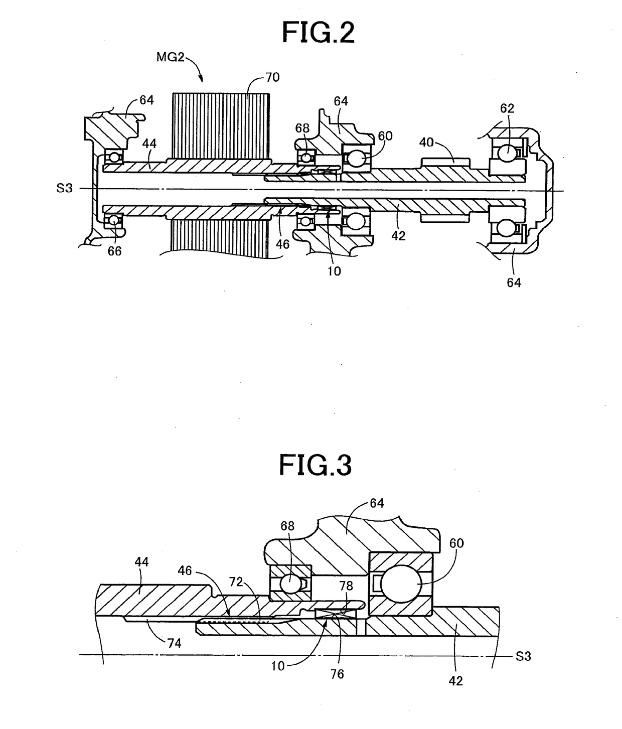
[0024]Reference is first made to FIG. 1, which is the schematic view showing a vehicular power transmitting system 12 provided with a friction damper 10 according to a first embodiment of this invention. This schematic view is a development view showing a plurality of axes S1-S4 of the power transmitting system 12 in the same plane. The power transmitting system 12 is a transaxle of a hybrid vehicle such as an FF vehicle of a transversely-mounted engine type wherein the axes S1-S4 extend in the transverse or width direction of the vehicle. On the first axis S1, there are disposed an engine 16, a damper device 18 and an input shaft 22 such that the input shaft 22 is connected to the engine 16 through the damper device 18. Coaxially with this first axis S1, there are disposed a planetary gear set 24 of a single-pinion type, and a first motor / generator MG1. The planetary gear set 24 and the first motor / generator MG1 cooperate to function as an electric differential portion 26. The plan...

second embodiment

[0039]In the first embodiment, the thick-walled section 86 is provided in a part of the axial length of the rear extending portion 82a of the rubber body 82. In a friction damper 100 according to the present second embodiment shown in FIG. 6, however, a thick-walled section 102 is provided in an entire axial length of the rear extending portion 82a. The thick-walled section 102 has a wall thickness larger than the wall thickness t2 of the constant-thickness section 88. It is noted that the wall thickness t2 of the front portion 82b may be changed within a range not larger than the smallest wall thickness of the thick-walled section 102.

third embodiment

[0040]In the friction damper 10 according to the first embodiment, the core member 80 is fixedly press-fitted in pressing contact with the outer circumferential surface 76 of the inner shaft in the form of the gear shaft 42. In a friction damper 110 according to the present third embodiment shown in FIG. 7, however, a core member 112 is fixedly press-fitted in pressing contact with the inner circumferential surface 78 of the outer shaft in the form of the rotor shaft 44. In this friction damper 110, the elastic body in the form of a rubber body 114 is bonded to the inner circumferential surface of the core member 112, unlike the rubber body 82 in the first embodiment. The rubber body 114 has an axial length L1 larger than an axial length L2 of the core member 112, and includes a rear extending portion 114a which extends in the rearward direction away from the rear end of the core member 112 as seen in the direction A in which the gear shaft 42 is moved relative to the rotor shaft 44...


PUM


Abstract

A friction damper comprising a cylindrical core member and a cylindrical elastic body bonded to an inner or outer circumferential surface of the core member, the core member being disposed within an annular space between an outer circumferential surface of an inner shaft and an inner circumferential surface of an outer shaft, which outer and inner circumferential surfaces are held in spline-fitting with each other, the core member being fixed to one of the inner and outer shafts, while the elastic body being disposed in pressing contact with the other of the inner and outer shafts, with compressive deformation of the elastic body, wherein the elastic body has an axial length larger than that of the core member, and includes an extending portion extending in its axial direction away from the core member, and wherein the extending portion of the elastic body has a thick-walled section which extends in a radial direction of the elastic body away from the core member and has a larger wall thickness than a section of the elastic body which overlaps the core member in an axial direction of the core member, the thick-walled section being held in pressing contact with the above-indicated other of the inner and outer shafts.

Description

[0001]This application claims priority from Japanese Patent Application No. 2017-030261 filed on Feb. 21, 2017, the disclosure of which is herein incorporated by reference in its entirety.FIELD OF THE INVENTION[0002]The present invention relates a friction damper, and more particularly to a friction damper having a spline fitting portion a tooth butting noise of which is reduced.BACKGROUND OF THE INVENTION[0003]There is known a friction damper including a cylindrical core member, and a cylindrical elastic body bonded to an inner or outer circumferential surface of the core member. The core member is disposed in an annular space between an outer circumferential surface of an inner shaft and an inner circumferential surface of an outer shaft while the inner and outer shafts are disposed concentrically and spline-fitted, such that the core member is fixed to one of the inner and outer shafts, while the elastic body is disposed in pressing contact with the other of the inner and outer s...

Claims


Application Information

Patent Timeline
Patent Type & Authority Applications(United States)
IPC IPC(8): F16F15/129F16F15/12
CPCF16F15/129F16F15/1201B60K6/40B60K6/445F16D3/12F16F1/371F16F15/1292H02K7/10F16D2001/103Y02T10/62Y10S277/912Y10T403/7026Y10T403/7028
Inventor TAKEKAWA, HIROSHI
Owner TOYOTA JIDOSHA KK
Learn More