Drive device with circulation filtering

Active Publication Date: 2018-08-23
LIEBHERR COMPONENTS BIBERACH GMBH
View PDF7 Cites 0 Cited by
  • Summary
  • Abstract
  • Description
  • Claims
  • Application Information

AI Technical Summary

Benefits of technology

This patent describes a pump system for a transmission that includes a circulation pump integrated into a housing section. The pump wheel is rotatably accommodated in the pump chamber and the transmission lubricant is conveyed in the pump conduit. The pump wheel can be attached to a transmission element without requiring additional gear wheels, minimizing wear and tear. The pump wheel can be easily accessed for maintenance by detachably connecting the housing section containing the pump wheel to the rest of the transmission housing body. The design of the pump wheel allows for equal lubricant conveyance even when the direction of rotation alternates. The pump wheel can be attached to a planetary gear of a transmission, such as its sun wheel or annulus gear, depending upon which transmission element provides the appropriate rotational speed for the pump wheel.

Problems solved by technology

In this kind of pivot drive, the quality and degree of contamination of the transmission lubricant—usually lubricating oil that may be supplemented with additives—exerts a significant influence on the wear behavior and thus also on the service life of the drive device.
As a result of the circulation pump that is required for this kind of circulation filtering, however, susceptibility to wear increases again, since the circulation pump itself forms a further sub-assembly and requires additional drive components to operate it, such as gear stages, couplings and the like, which are in turn subject to wear.
If the circulation pump or an associated accessory sub-assembly, such as a pump bearing, a spur gear stage for driving the pump or the like, fails, this results in a failure of the entire drive device, and so the service life yielded by the lubricant filtration itself and the correspondingly reduced wear in the transmission will all be nullified by any wear of the additional components of the circulation filter device.
A further problem with the use of circulation pumps of this type arises from the bidirectional driving direction of the pivot drives.
Meanwhile, if the circulation pump is no longer coupled to the engine or the transmission but is driven instead by a separate drive, such as an electric drive, then further additional components are again needed, which are themselves associated with an increased susceptibility to wear.

Method used


Image

  • Drive device with circulation filtering
  • Drive device with circulation filtering
  • Drive device with circulation filtering

Examples


Embodiment Construction

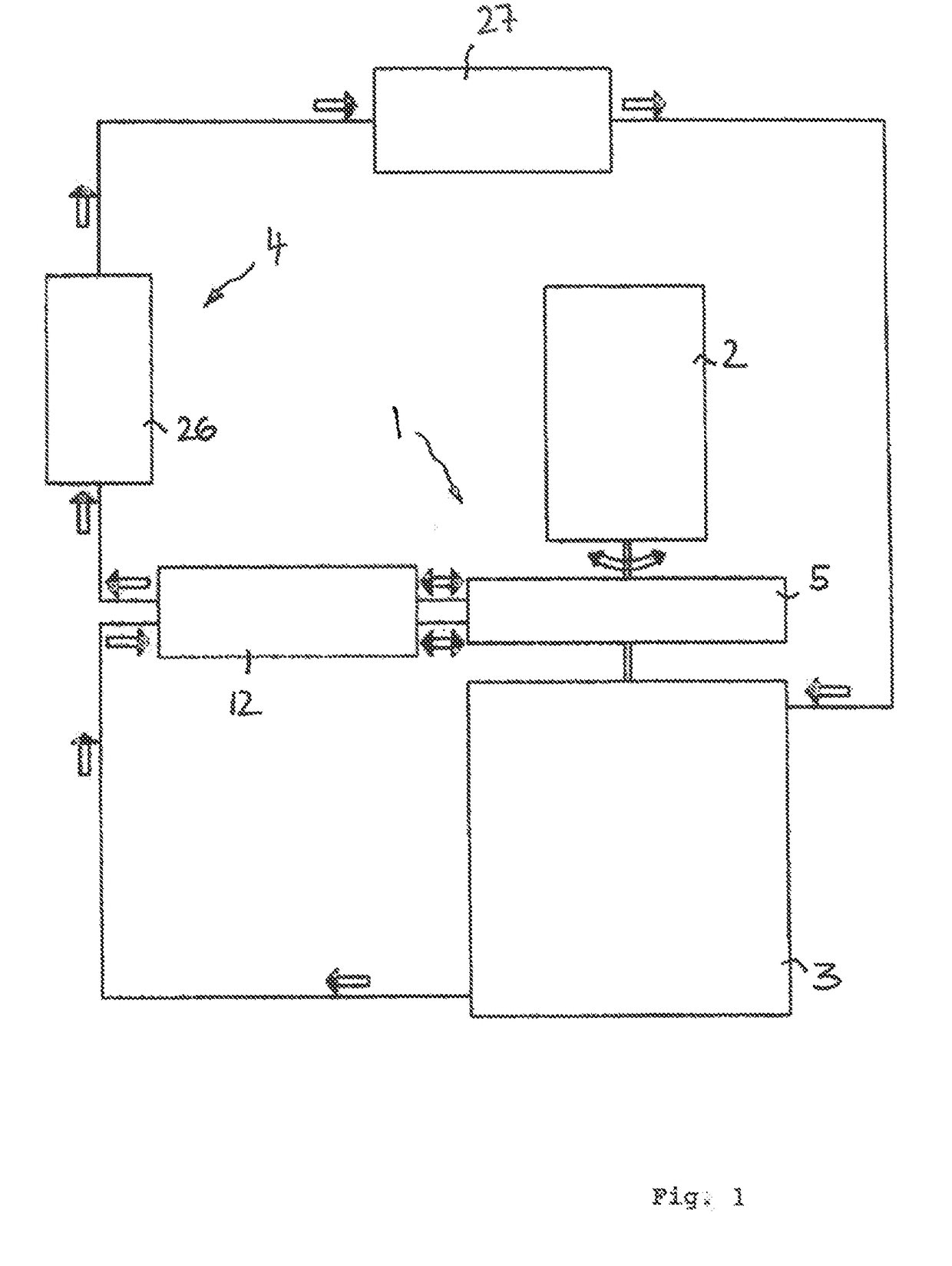
[0029]As FIG. 1 shows, the drive device 1 comprises an engine 2 and a transmission 3 that is connected to it, wherein the engine 2 and the transmission 3 can be installed in a mutually coaxial, successive arrangement. An engine output shaft can form the transmission input shaft and vice versa, or a central transmission and / or engine shaft 23 connects the engine 2 with the transmission 3 and defines the central longitudinal axis 22. As FIG. 4 shows, the drive device 1 can form a body that is elongate overall and approximately tower-shaped and that extends along the straight central longitudinal axis 22.

[0030]The transmission 3, which is connected to the engine 2 on the input side, has an output pinion 24 on the output side, for example, which can, for example, protrude laterally on the end section of the transmission 3 facing away from the engine 2 or can protrude from the transmission housing 9, for instance in order to intermesh with a large sprocket wheel such as those used on the...


PUM


Abstract

The invention relates to a drive device, in particular in the form of a pivot drive for material-transferring devices such as mining excavators, comprising an engine, a transmission that is connected to the engine and is lubricated by a transmission lubricant, and a circulation filter device for filtering the transmission lubricant in circulation, wherein the circulation filter device has at least one circulation pump for circulating the transmission lubricant. According to the invention, the circulation pump is integrated into the transmission, wherein the pump wheel of the circulation pump is configured as a peripheral wheel and is arranged for conjoint rotation with a transmission element.

Description

CROSS-REFERENCE TO RELATED APPLICATIONS[0001]The present application is a continuation of International Application No. PCT / EP2016 / 001555, filed Sep. 16, 2016, which claims priority to German Patent Application No. 10 2015 012 132.4, filed Sep. 17, 2015, both of which are incorporated by reference herein in their entireties.BACKGROUND1) Technical Field[0002]The invention relates to a drive device, in particular in the form of a pivot drive for material-transferring devices such as mining excavators, comprising an engine, a transmission that is connected to the engine and is lubricated by a transmission lubricant, and a circulation filter device for filtering the transmission lubricant in circulation, wherein the circulation filter device has at least one circulation pump for circulating and filtering the transmission lubricant.2) Description of the Related Art[0003]Pivot drives of this type, which usually have a hydraulically driven engine with a transmission that is connected to it...

Claims


Application Information

Patent Timeline
IPC IPC(8): F16H57/04F04D29/18F16H57/031E02F9/12E02F9/20
CPCF16H57/0441F04D29/181F16H57/0404F16H57/0436F16H57/031F16H57/0482E02F9/126E02F9/202
Inventor MARQUARD, PHILIPPWIDMANN, ROLAND
Owner LIEBHERR COMPONENTS BIBERACH GMBH
Why Eureka
Try Eureka