Check patentability & draft patents in minutes with Patsnap Eureka AI!

Remote control robot system

a robot and remote control technology, applied in the field of remote control robot systems, can solve the problems of difficult robotic arm manipulation, robot arm to perform the work with sufficient accuracy, and operator is not able to grasp the spatial relationship between a work object and the robot only in one direction, and achieve the effect of easy switching

Active Publication Date: 2018-08-30
KAWASAKI HEAVY IND LTD
View PDF5 Cites 4 Cited by
  • Summary
  • Abstract
  • Description
  • Claims
  • Application Information

AI Technical Summary

Benefits of technology

This patent proposes a system that allows an operator to remotely manipulate a robot to perform delicate tasks or in changing environments. The system uses a combination of highly accurate industrial robots and precise manipulation instructions from the operator to achieve efficient and precise work.

Problems solved by technology

In such a remote control robot system, if only one camera which images the work environment is provided, the operator is not able to grasp a spatial relationship between a work object and the robot only in one direction.
Thus, it is difficult for the operator to manipulate the robotic arm and cause the robotic arm to perform the work with sufficient accuracy.

Method used


Image

  • Remote control robot system
  • Remote control robot system
  • Remote control robot system

Examples


first embodiment

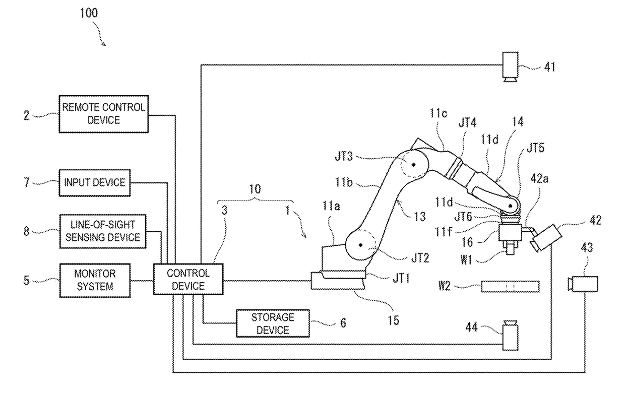
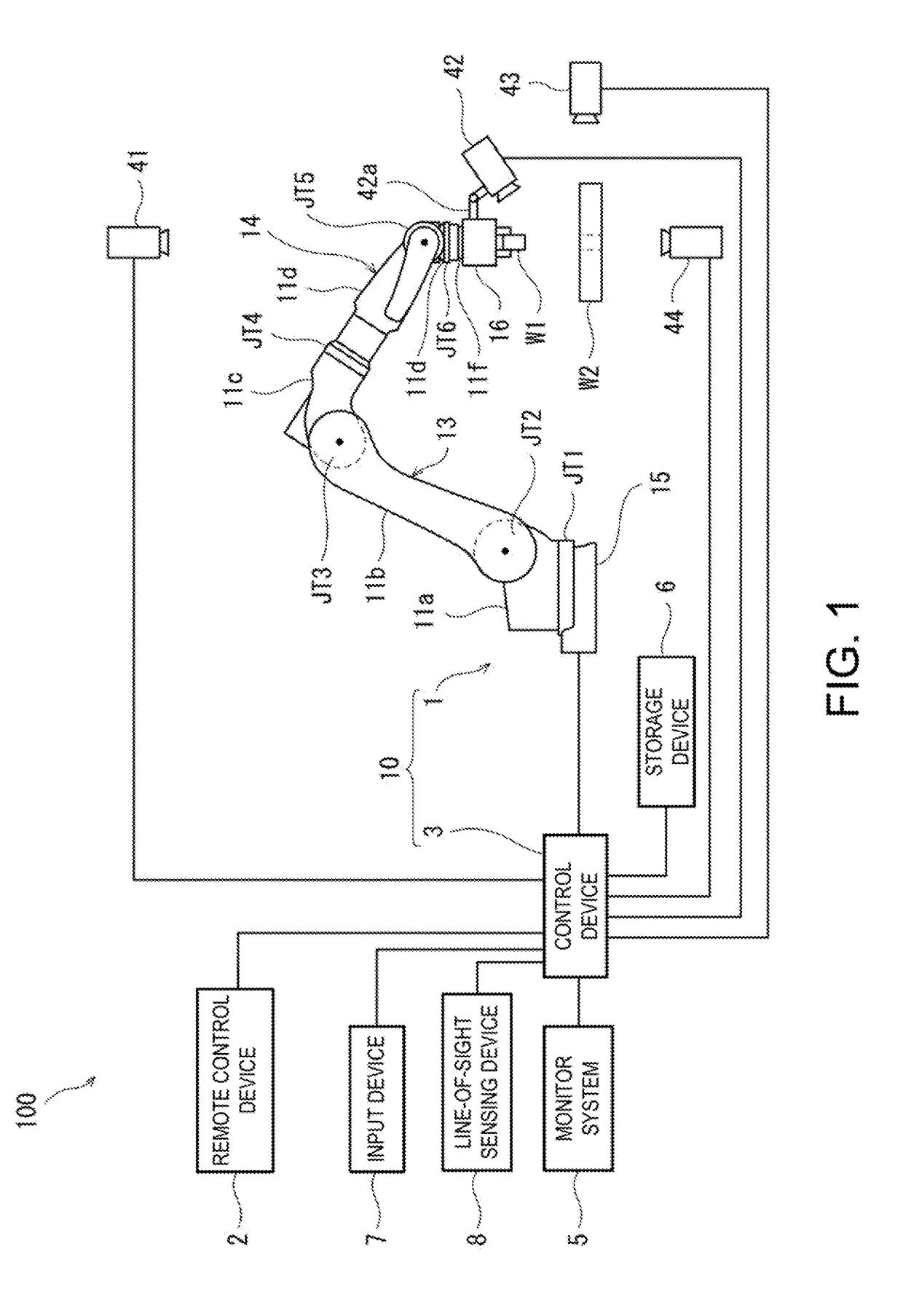
[0016]Hereinafter, a remote control robot system according to a first embodiment of the present disclosure is described with reference to the accompanying drawings. The robot system 100 according to this embodiment is a system including a robotic arm 1 which repeatedly perform a given work, and a remote control device 2 which remotely manipulates the robotic arm 1 by manual operation. In the robot system 100, an operator who is located at a position distant from a workspace of the robotic arm 1 (outside of the workspace) is able to manually operate or manipulate the remote control device 2 to input instructions so that the robotic arm 1 performs operation corresponding to the instructions to perform a specific work. In addition, in the robot system 100, the robotic arm 1 is also capable of automatically performing the given work without the operator manipulating the remote control device 2.

[0017]An operating mode in which the robotic arm 1 is operated according to the instructions i...

second embodiment

[0058]Next, with reference to FIG. 3, a remote control robot system according to a second embodiment is described. Note that, in this embodiment, the same reference characters are given to the same component as the first embodiment to omit redundant description.

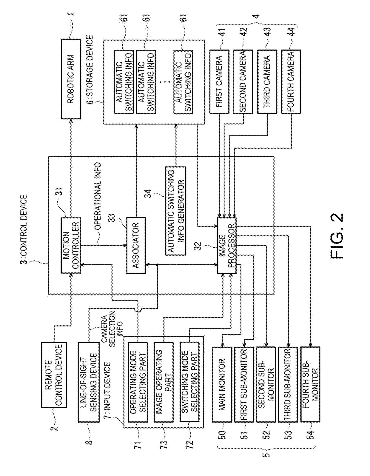
[0059]FIG. 3 is a schematic diagram illustrating a configuration of a control system of the remote control robot system according to the second embodiment. In this embodiment, the system is provided with a camera selecting part 74 by which the input device 7 functions as the camera selecting device, instead of the line-of-sight sensing device 8 of the first embodiment. Also in this embodiment, although the input device 7 is a tablet terminal, it is not limited to this configuration, similar to the first embodiment. The camera selecting part 74 receives a selection of one camera from the first to fourth cameras 41-44 by a manual operation from an operator. Then, the camera selecting part 74 generates the camera selection infor...


PUM


Abstract

A remote control robot system is provided, which includes robotic arm configured to perform a given work, remote control device for an operator to remotely manipulate operation of robotic arm, plurality of cameras configured to image the work of robotic arm, monitor configured to display a captured image that is sent, camera selecting device configured to generate, in response to receiving an operator's selection of one camera from the plurality of cameras, camera selection information for switching captured image displayed on monitor to captured image from selected camera, storage device configured to store information where operational information related to operation of robotic arm in work is associated with camera selection information, as automatic switching information, and an image processor configured to send to monitor the captured image from camera selected from plurality of cameras based on automatic switching information stored in storage device.

Description

TECHNICAL FIELD[0001]The present disclosure relates to a remote control robot system.BACKGROUND ART[0002]Conventionally, industrial robots are used for an iterative work, such as an assembling work of a component. The industrial robot is capable of automatically performing a taught operation at high speed and with sufficient accuracy by being taught information required for the work. However, when performing a work requiring a delicate positioning or a work environment is changed, it may be advantageous that an operator performs the work by remotely manipulating the robot, rather than the robot performs the work automatically. Patent Document 1 proposes a remote control robot system which is capable of operating a robot based on manipulating instructions from the operator.[0003]The remote control robot system disclosed in Patent Document 1 includes a camera which images a work environment, and a display device which displays a captured image which is imaged by the camera, and it is ...

Claims


Application Information

Patent Timeline
IPC IPC(8): B25J13/00B25J19/04B25J19/02H04N7/18H04N5/232
CPCB25J13/00B25J19/04B25J19/023H04N7/181H04N5/23219Y10S901/02G05B2219/40195G05B2219/39004G05B2219/39439G05B19/4182G05B2219/39102G05B2219/40022B25J9/1689G05B2219/40136G05B2219/40142G05B2219/40146G05B2219/40161G05B2219/40162G05B2219/40169G05B2219/40183G05B2219/40163G05B2219/40627G05B2219/39533G05B2219/40145G05B2219/40143G05B2219/40134G05B2219/40139G05B2219/35464G05B2219/40182G05B2219/39531B25J9/1674G05B2219/33007G05B2219/37297G05B2219/40387B25J3/04B25J13/025B25J9/16B25J9/1692B25J9/1682B25J9/1669B25J9/0087B25J9/1641B25J9/1638H04N23/611B23P19/04B23P21/00B25J9/0084B25J9/1697B25J13/006B25J13/08Y10S901/09Y10S901/47Y10S901/08B25J3/00B25J13/06B25J13/088B25J18/00B25J9/161B25J9/1664B25J9/1633B23Q15/12B25J9/1628B25J13/02B25J9/163Y10S901/03Y10S901/27B25J11/008Y10S901/41B25J13/003B25J13/065G06F3/017B25J13/084Y10S901/10Y10S901/46B25J9/1653B25J9/1612B25J19/028B25J9/1602B25J13/085B25J13/087A61B34/32A61B34/37G06T7/62G06T7/70B25J9/0081B25J9/1646B23P21/002
Inventor HASHIMOTO, YASUHIKOKAMON, MASAYUKI
Owner KAWASAKI HEAVY IND LTD
Features
  • R&D
  • Intellectual Property
  • Life Sciences
  • Materials
  • Tech Scout
  • Unparalleled Data Quality
  • Higher Quality Content
  • 60% Fewer Hallucinations
Learn More