Control device for vehicle

Inactive Publication Date: 2018-08-30
TOYOTA JIDOSHA KK
View PDF0 Cites 5 Cited by
  • Summary
  • Abstract
  • Description
  • Claims
  • Application Information

AI Technical Summary

Benefits of technology

[0006]It is therefore an object of the present invention to provide a contr

Problems solved by technology

Since the air-fuel ratio varies among the cylinders in the above-described temperature increase process, an increase in a fluctuation amount of the rotational speed of the internal combustion engine might increase vibration of the internal combustion engine.
If the

Method used


Image

  • Control device for vehicle
  • Control device for vehicle
  • Control device for vehicle

Examples


Embodiment Construction

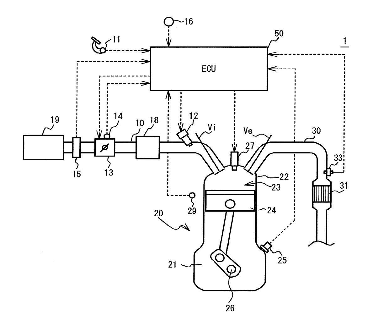
[0029]FIG. 1 is a schematic configuration diagram around an engine 20 in a vehicle 1. In the engine 20 burns the air-fuel mixture within a combustion chamber 23 in a cylinder head 22 arranged on a cylinder block 21 housing a piston 24, which causes the piston 24 to reciprocate. The reciprocating movement of the piston 24 is converted into the rotational movement of the crankshaft 26. Although the engine 20 is an in-line four-cylinder engine, it is not limited to this as long as it has multiple cylinders.

[0030]The cylinder head 22 of the engine 20 is provided with an intake valve Vi for opening and closing an intake port and an exhaust valve Ve for opening and closing an exhaust port for every cylinder. Also, the top of the cylinder head 22 is attached with an ignition plug 27 for igniting the air-fuel mixture in the combustion chamber 23 for every cylinder.

[0031]An intake port of each cylinder is connected to a surge tank 18 via a branch pipe of each cylinder. An intake pipe 10 is c...


PUM


Abstract

A control device for a vehicle includes a resonance suppressor configured to control any one of a temperature increase process, a slip amount of a lock-up clutch, and a gear position of a transmission to execute a resonance suppression process suppressing resonance of an internal combustion engine and the transmission caused by execution of the temperature increase process, when the temperature increase process is requested, when the lock-up clutch is in the engaged state, and when rotational speed of the internal combustion engine falls in a resonance region in which the internal combustion engine resonates with the transmission if the temperature increase process is executed.

Description

CROSS-REFERENCE TO RELATED APPLICATION[0001]This application is based upon and claims the benefit of priority of the prior Japanese Patent Application No. 2017-037508, filed on Feb. 28, 2017, the entire contents of which are incorporated herein by reference.FIELD OF THE INVENTION[0002]The present invention relates to a control device for a vehicle.BACKGROUND[0003]There is known an increase temperature process that controls an air-fuel ratio of one of plural cylinders of an internal combustion engine to be a rich air-fuel ratio and controls air-fuel ratios of the other cylinders to be lean air-fuel ratios, in order to increase a temperature of a catalyst for purifying exhaust gas from the internal combustion engine (See, for example, Japanese Laid-Open Patent Publication No. 2012-057492).[0004]Further, a vehicle with an internal combustion engine is equipped with a fluid transmission device having a lock-up clutch for switching an engaged state and a released state to control power t...

Claims


Application Information

Patent Timeline
IPC IPC(8): B60W30/184
CPCB60W30/184B60W2030/206B60W2030/203B60W2510/0241B60W2510/068B60W2040/1392B60W10/02B60W10/06B60W10/10B60W50/00B60W2710/026B60W2710/0622B60W2710/1005B60W10/026B60W30/20B60W2510/0233B60W2510/0638B60W2530/12F02D41/0085F02D41/022F02D41/025F02D2250/28Y02T10/12Y02A50/20
Inventor KATAYAMA, AKIHIRO
Owner TOYOTA JIDOSHA KK
Why Eureka
Try Eureka