
Shearable riser system and method

a riser and shear technology, applied in the direction of drilling casings, drilling pipes, borehole/well accessories, etc., can solve the problems of severe equipment damage, more design and implementation requirements of sea-based wells, and high cost of subsea wells, so as to facilitate tubular entry.

Active Publication Date: 2018-08-30
DZIEKONSKI MITCHELL Z
View PDF11 Cites 1 Cited by
  • Summary
  • Abstract
  • Description
  • Claims
  • Application Information

AI Technical Summary

Benefits of technology

The patent text discusses the challenges of drilling and servicing wells in subterranean environments, particularly in sea-based wells which are more costly and challenging. The text highlights the need for improvements in riser structures to prevent damage to subsea equipment in case of extreme events such as the loss of control of the vessel or platform, extreme weather conditions, or extreme wave events. The technical effect of the patent text is to provide a solution that can protect subsea equipment from damage during extreme events and minimize risks associated with drilling and servicing wells in subterranean environments.

Problems solved by technology

Particular challenges are posed by both environments, and in many cases the sea-based wells are more demanding in terms of design and implementation.
Subsea wells tend to be much more costly, both due to the depths of water beneath which the well lies, as well as for the environmental hazards associated with drilling, completion, and extraction in sensitive areas.
In extreme conditions, however, the risers may transmit forces to the equipment on the sea floor that can cause severe damage to the equipment.

Method used


Image

  • Shearable riser system and method
  • Shearable riser system and method
  • Shearable riser system and method

Examples


Embodiment Construction

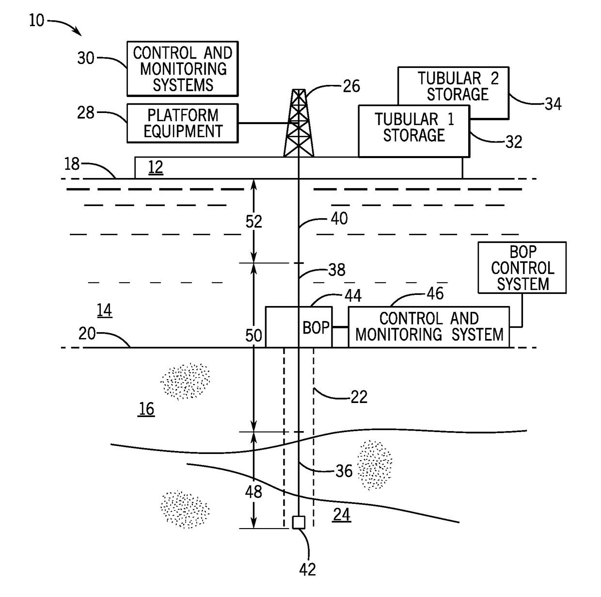
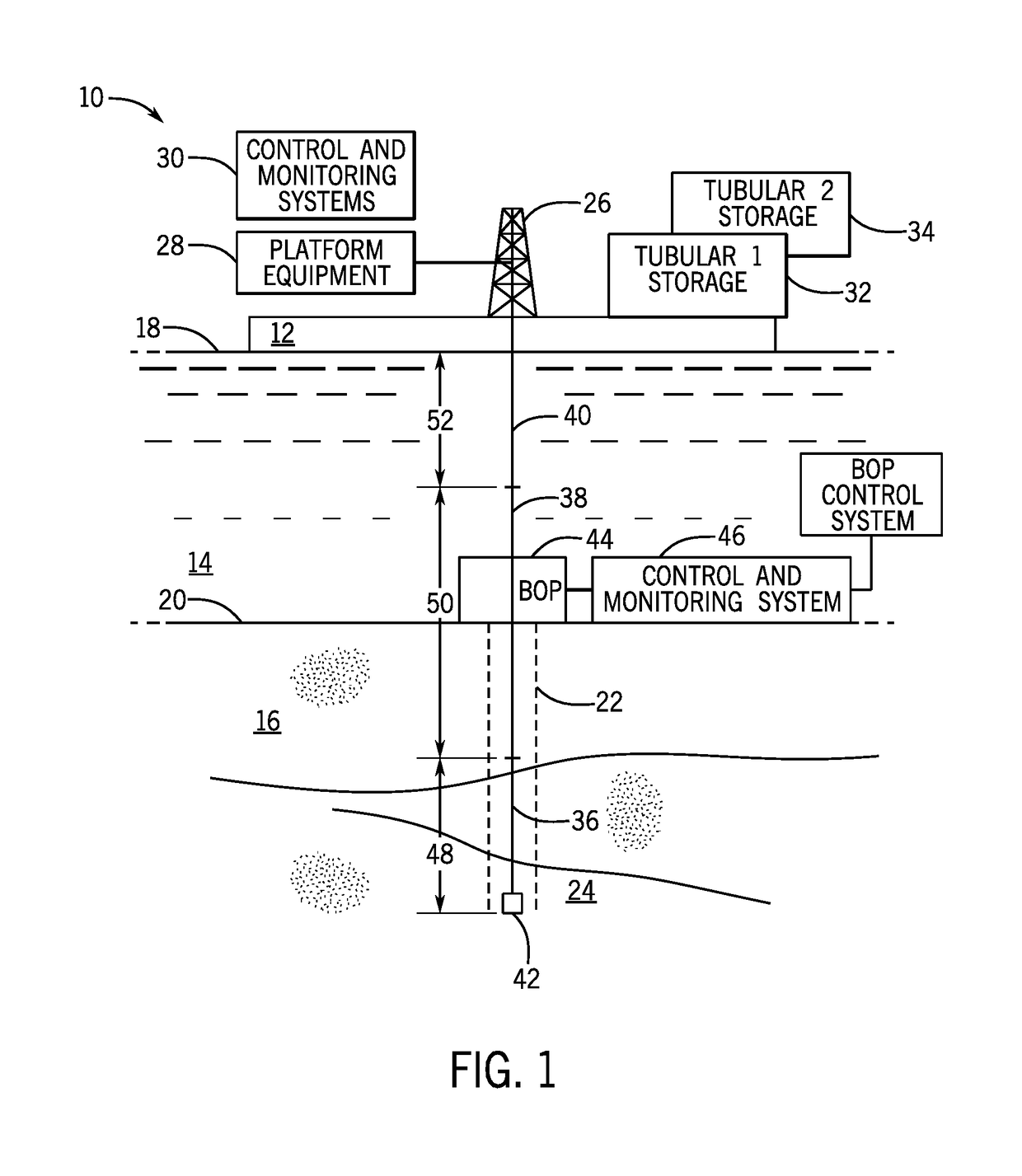
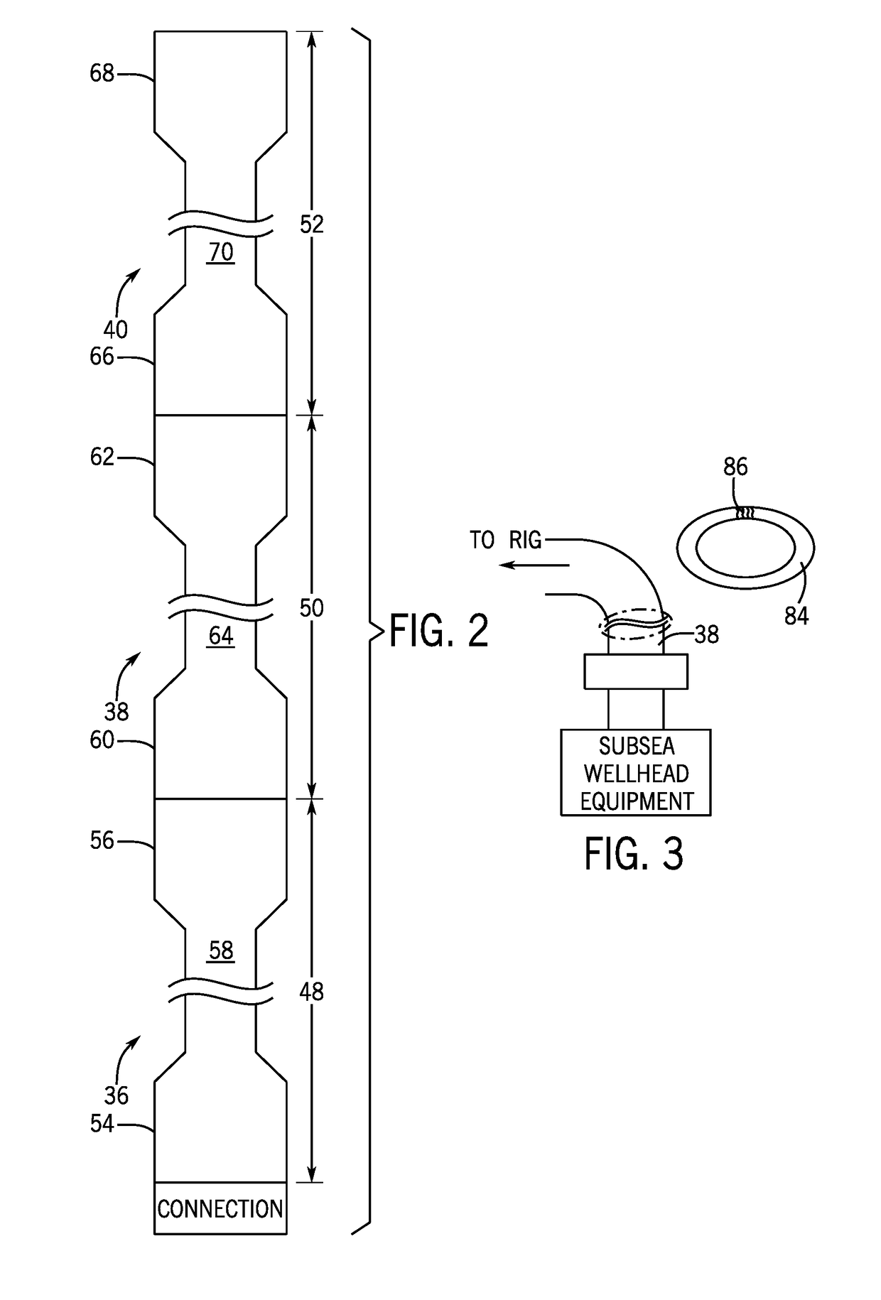
[0012]Turning now to the drawings, and referring first to FIG. 1, a well system is illustrated and designated generally by the reference numeral 10. The system is illustrated as an offshore operation comprising a vessel or platform 12 that would be secured to, anchored, moored or dynamically positioned in a stable location in a body of water 14. In FIG. 1, the underlying ground or earth 16 (in this case the seabed) is illustrated below the platform, with the surface of the water designated by the reference numeral 18, and the surface of the earth by reference numeral 20. The platform will typically be positioned near or over one or more wells 22. One or more subterranean horizons of interest 24 will be penetrated or traversed by the well, such as for probing, extraction, accessing or otherwise servicing, depending upon the purpose of the well. In many applications, the horizons will hold minerals that will ultimately be produced form the well, such as oil and / or gas. The platform ma...


PUM


Abstract

A riser for a subsea well comprises a first riser section that may be similar to conventional risers in design and material specifications. A second riser section comprises a passive fracture section that is specifically designed to shear or fracture under design conditions, such as extreme events (e.g., extreme weather or waves, loss of control of a rig or vessel, a rig or vessel moving from a desired position). The passive fracture section is designed to fracture first to prevent or minimize damage to other well equipment, such as at the seabed.

Description

CROSS-REFERENCE TO RELATED APPLICATIONS[0001]This application claims priority from and the benefit of U.S. Provisional Application Ser. No. 62 / 464,031, entitled “Shearable Riser System and Method,” filed Feb. 27, 2017, which is hereby incorporated by reference in its entirety.BACKGROUND[0002]The invention relates generally to riser structures used in marine oil and gas applications.BRIEF DESCRIPTION[0003]The development of technologies for exploration for and access to minerals in subterranean environments has made tremendous strides over past decades. While wells may be drilled and worked for many different reasons, of particular interest are those used to access petroleum, natural gas, and other fuels. Such wells may be located both on land and at sea. Particular challenges are posed by both environments, and in many cases the sea-based wells are more demanding in terms of design and implementation. Subsea wells tend to be much more costly, both due to the depths of water beneath ...

Claims


Application Information

Patent Timeline
IPC IPC(8): E21B17/01E21B33/03E21B43/013
CPCE21B17/01E21B33/03E21B43/013E21B33/038E21B17/06
Inventor DZIEKONSKI, MITCHELL Z.
Owner DZIEKONSKI MITCHELL Z
Learn More