Method for forming planarized etch mask structures over existing topography

a topography and etching technology, applied in the field of forming planarized etching mask structures over existing topography, can solve the problem of becoming more difficult to maintain the aspect ratios necessary for high fidelity pattern transfer, and achieve the effect of reducing the collapse of features

Active Publication Date: 2018-08-30
CANON KK
View PDF2 Cites 5 Cited by
  • Summary
  • Abstract
  • Description
  • Claims
  • Application Information

AI Technical Summary

Benefits of technology

[0018]In a particular embodiment, the multi-layer stack has a composite effective mechanical stiffness (Eeff) sufficient to maintain 50 nm or smaller features at aspect ratios of 5:1 or more with minimal feature collapse.

Problems solved by technology

However, as feature sizes shrink to dimensions less than 100 nanometers, it becomes more difficult to maintain the aspect ratios necessary for high fidelity pattern transfer, particularly when other factors such as topography variations on the existing substrate surface are introduced.

Method used


Image

  • Method for forming planarized etch mask structures over existing topography
  • Method for forming planarized etch mask structures over existing topography
  • Method for forming planarized etch mask structures over existing topography

Examples


Embodiment Construction

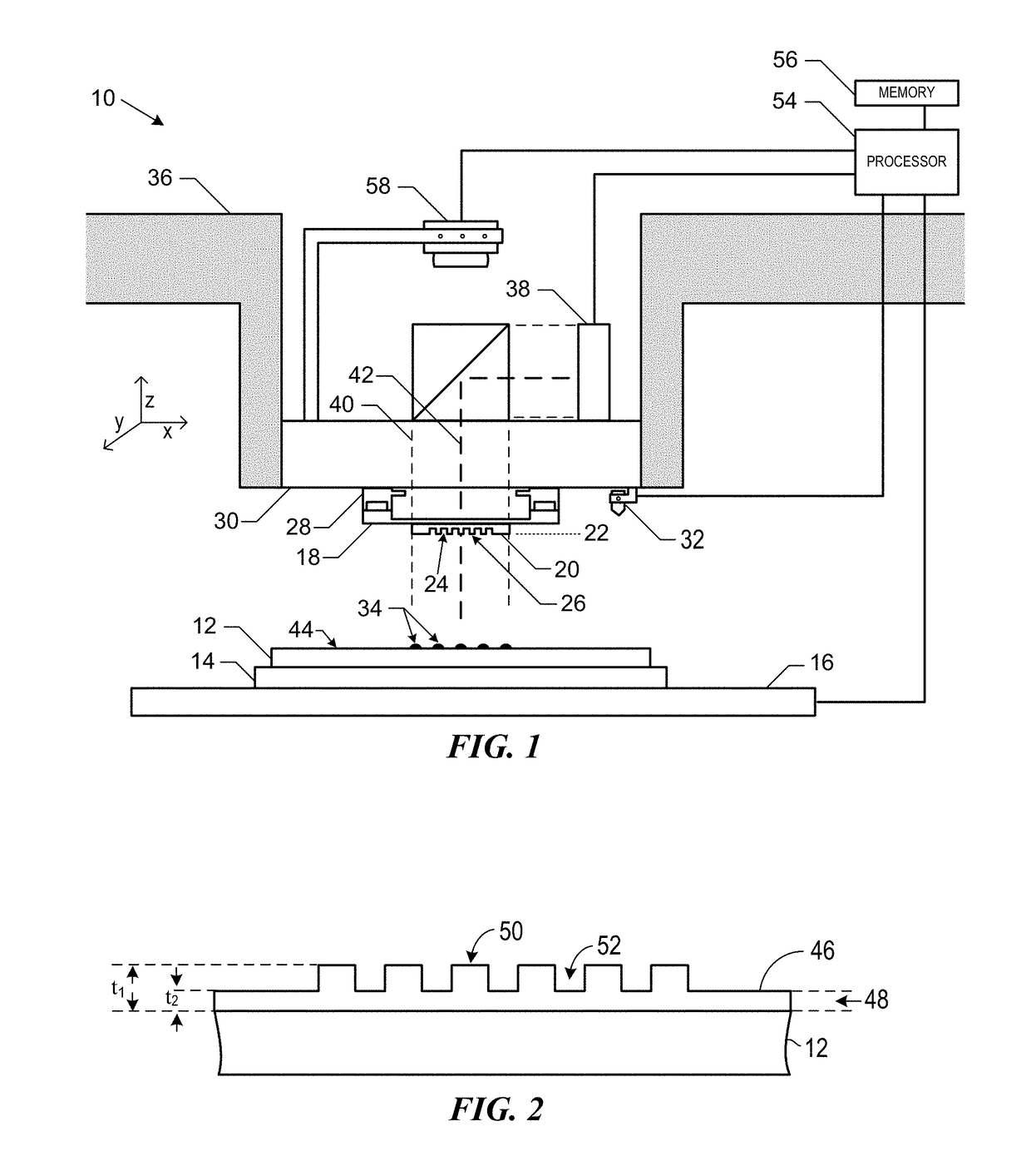
[0035]As previously noted, patterned features can be formed by a number of different lithographic techniques including photolithography, nanoimprint lithography, extreme ultraviolet lithography and electron beam lithography, and the like. The pattern features are used as an etch mask to define a pattern transferred into an underlying material, film or substrate. An exemplary nanoimprint lithography system is illustrated in FIG. 1. Nanoimprint lithography system 10 can be used to form a relief pattern on substrate 12. Substrate 12 may be coupled to substrate chuck 14. As illustrated, substrate chuck 14 is a vacuum chuck. Substrate chuck 14, however, may be any chuck including, but not limited to, vacuum, pin-type, groove-type, electrostatic, electromagnetic, and / or the like. Exemplary chucks are described in U.S. Pat. No. 6,873,087, which is hereby incorporated by reference herein.

[0036]Substrate 12 and substrate chuck 14 may be further supported by stage 16. Stage 16 may provide tra...


PUM

PropertyMeasurementUnit
feature sizeaaaaaaaaaa
heightaaaaaaaaaa

Abstract

A method used to create small pattern features over existing topography variations. The method includes providing a substrate having a surface having non-planar surface variations; forming a multi-stack layer over the substrate, by applying a first carbon layer over the substrate, with the resultant first carbon layer having non-planar surface variations corresponding to the non-planar surface variations of the underlying substrate, followed by applying a second planarizing layer over the first carbon layer; depositing a hard mask on the multi-stack layer; forming a patterned layer on the hard mask, the formed patterned layers having features; and performing one or more etch steps to etch the formed patterned layer features into the multi-layer stack. The multi-layer stack has a composite effective mechanical stiffness (Eeff) sufficient to maintain the one or more etched features with minimal feature collapse.

Description

BACKGROUND INFORMATION[0001]Nano-fabrication includes the fabrication of very small structures that have features on the order of 100 nanometers or smaller. One application in which nano-fabrication has had a sizeable impact is in the processing of integrated circuits. The semiconductor processing industry continues to strive for larger production yields while increasing the circuits per unit area formed on a substrate; therefore nano-fabrication becomes increasingly important. Nano-fabrication provides greater process control while allowing continued reduction of the minimum feature dimensions of the structures formed.[0002]Exemplary nano-fabrication techniques in current use for patterning the features that form these structures include optical lithography, photolithography, nanoimprint lithography, extreme ultraviolet lithography and electron beam lithography, and the like. However, as feature sizes shrink to dimensions less than 100 nanometers, it becomes more difficult to maint...

Claims


Application Information

Patent Timeline
Patent Type & Authority Applications(United States)
IPC IPC(8): H01L21/308H01L21/311H01L21/02H01L21/3105H01L21/027
CPCH01L21/3081H01L21/3086H01L21/31111H01L21/0273H01L21/02282H01L21/31051H01L21/3088H01L21/02115H01L21/0332H01L21/0337H01L21/0274G03F7/0002H01L21/76816
Inventor LABRAKE, DWAYNE L.RESNICK, DOUGLAS J.
Owner CANON KK
Why Eureka
Try Eureka