Component building system

a technology of building systems and components, applied in building components, building constructions, constructions, etc., can solve the problems of high amount of skilled labor requirements and complexity of building structures, low system acceptance, and insufficient cost reduction of systems, so as to improve construction speed, reduce construction costs, and improve thermal performan

Inactive Publication Date: 2014-09-18
BUI THUAN
View PDF21 Cites 5 Cited by
  • Summary
  • Abstract
  • Description
  • Claims
  • Application Information

AI Technical Summary

Benefits of technology

[0010]Accordingly, it is therefore an object of the present invention to provide a new building component system that is low cost and simple for single store to high-rise structure and that has faster construction time, higher thermal performance, and more culturally acceptable features, particularly for developing countries where developers or general contractors often do not have the excess capital for heavy equipment for traditional load-bearing precast systems.

Problems solved by technology

The major problems of many site building methods are their high amount of skilled labor requirements and complexity of the building structures.
In cases where the building system is too foreign to the local market, system acceptance will be very low.
However, no system can reduce cost sufficiently, increase construction speed, provide more energy-efficient envelope, and have more culturally acceptable features at the same time.
However, a typical load-bearing wall system inherently has limitations in application and practice in most developing markets.
For example, a typical precast system requires a large amount of capital for heavy equipment to manufacture and handle its panel components, making it a very unattractive investment relative to traditional cast-in-place system which is more easily practiced and implemented without heavy machinery.
However, the traditional cast-in-place concrete system, as shown, for example, in FIGS. 1A-1B, also has its weaknesses.
Its biggest weakness lies in the construction of walls and partitions between load-bearing columns 11.
Inherent major problems include slow construction speed, inconsistent quality and lack of insulation.
In most cases its energy and noise performance is far lower than precast insulated walls.
In the last few decades, another type of non-precast system using a light gauge steel frame and a thin sheathing has become an attractive alternative; however, acceptance has been very slow as most people in the developing market still prefer traditional masonry walls and do not like the flimsiness of its covering and its durability when compared to the traditional masonry walls.
Given the fact that at least 80% of 7 billion world population is living in developing countries and living mostly in traditional concrete frame housing, any precast system that does not resemble what people have been used to for generations and can offer better performance over traditional system will have little chance of acceptance and adoption.
In addition to being unfamiliar in the local engineering community and end users, the high level of initial capital investment required for precast systems will make them unviable as a solution.
Other non-concrete or non-masonry solutions have the same problem in their adaption as well.
Typical load-bearing precast system from developed countries will not be perceived by the mass population in developing countries as a better mouse trap because of its lack of resemblances.
This explains why most evolved precast building systems of the developed countries have failed in developing markets.
As a result, not too many people are willing to buy something that does not perceive as a better mouse trap than the one they grew up in.

Method used


Image

  • Component building system
  • Component building system
  • Component building system

Examples


Embodiment Construction

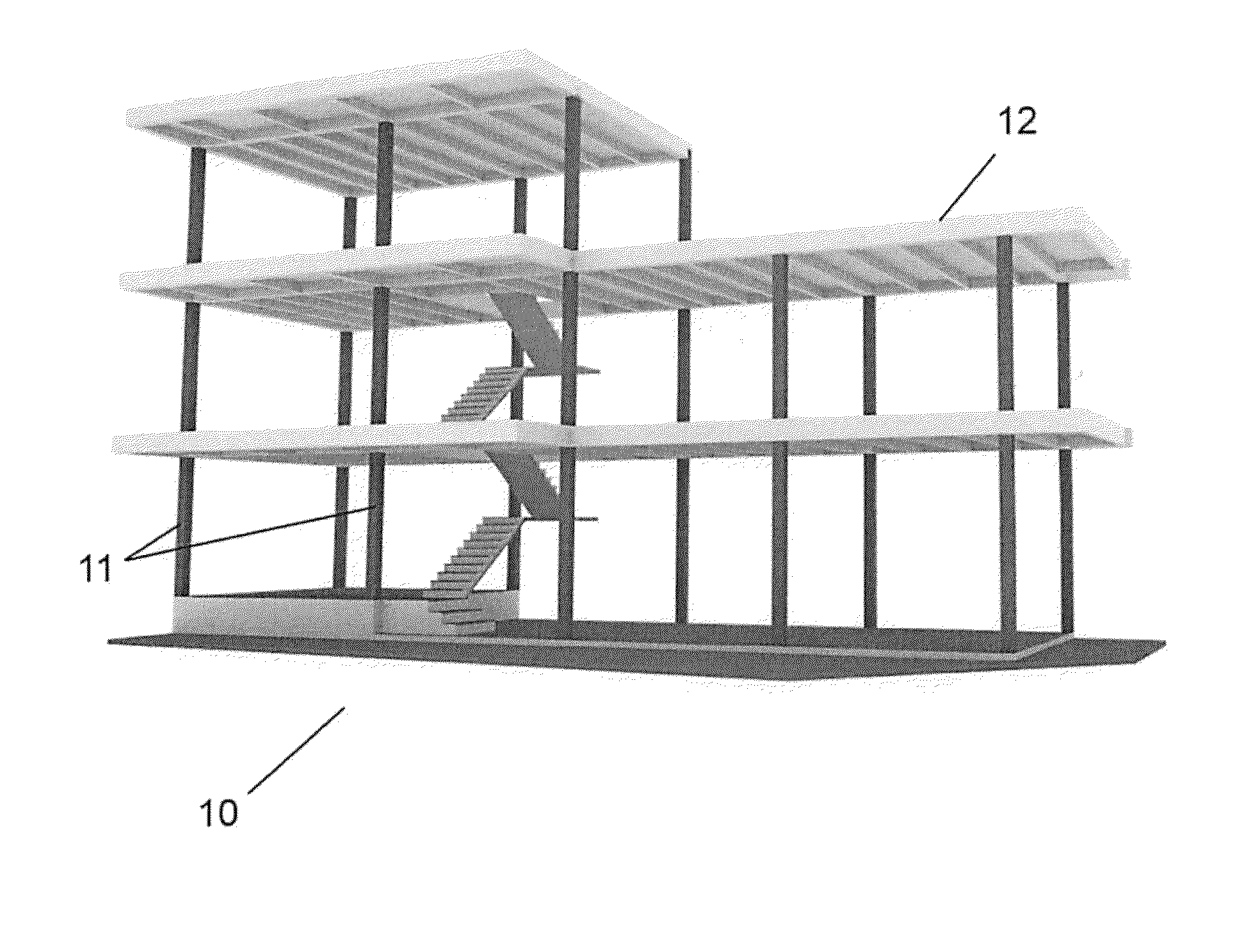
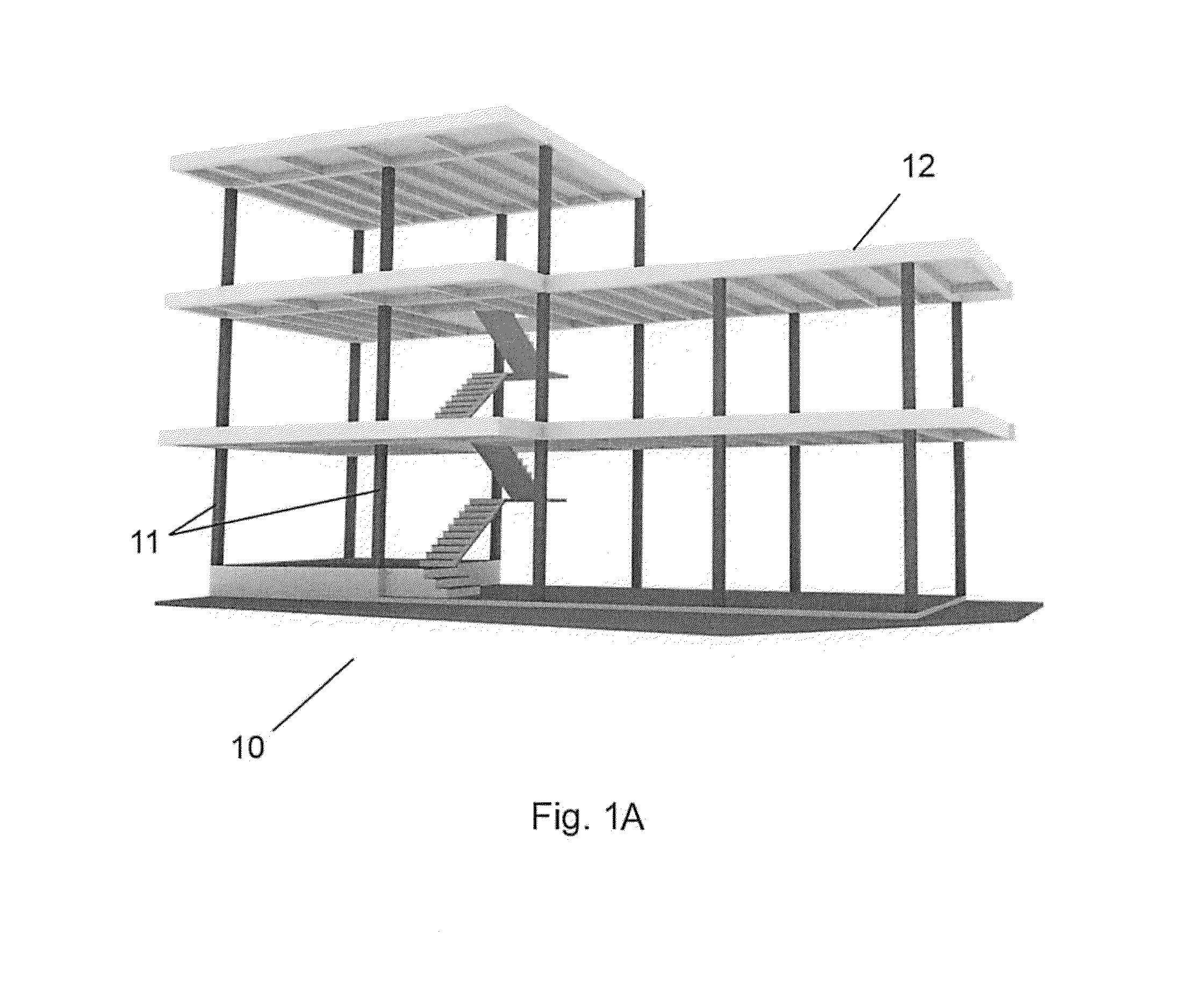
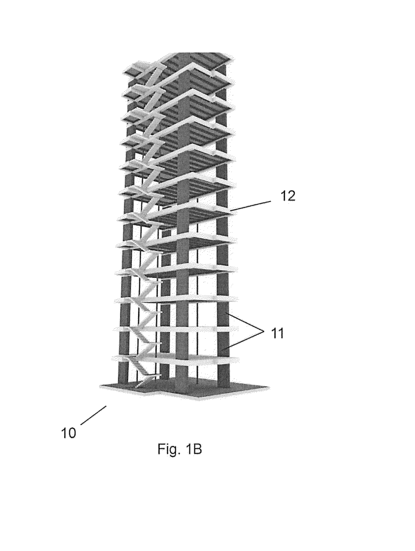
[0036]Referring now to FIG. 2 which illustrates a component precast system that is a hybrid building system designed to integrate both elements of precast and cast-in-place technologies and made possible by its precast wall panel design and specifications according to an embodiment of the present invention. As shown in FIG. 2, the component precast system comprises mainly lightweight precast wall panel components designed to span and connect between traditional concrete columns and beams in the traditional concrete superstructure 10 as shown in FIG. 1A and FIG. 1B. The wall panel component 20 is designed to be as light as possible (no more than 5 Ton) without concern to its load-bearing capacity. The concrete layer in panel can be of regular or lightweight concrete. Essentially, the precast wall panel 20 is designed as a cladding panel to replace the hundreds of concrete block or clay bricks between columns and provide higher performance walls.

[0037]As shown in FIG. 2 though FIG. 4,...


PUM


Abstract

A component building system combines both precast elements and cast-in-place elements that is cost effective, more cultural acceptance, and adaptable for constructing single story to high-rise building structures. The component building system comprises mostly open rib or closed sandwich wall panel components that are limited or non-load bearing panel connecting between main columns in the concrete frame superstructure.

Description

CROSS-REFERENCE TO RELATED APPLICATIONS[0001]This application is a non-provisional application of an earlier U.S. provisional patent application Ser. No. 61 / 852,398, filed on Mar. 16, 2013.FIELD OF INVENTION[0002]The invention relates to a precast building system and, more specifically, relates to the latest and best aspects of precast technology and incorporate the same in the traditional cast-in-place concrete frame system to produce a reliable, trusted and economical building solution for high speed and high volume production.BACKGROUND OF THE INVENTION[0003]Building structures are often built on site in most parts of the world. The problems of site constructions are well documented in past journal articles. The major problems of many site building methods are their high amount of skilled labor requirements and complexity of the building structures. In cases where the building system is too foreign to the local market, system acceptance will be very low. There are certainly many ...

Claims


Application Information

Patent Timeline
Patent Type & Authority Applications(United States)
IPC IPC(8): E04B1/16E04B1/21
CPCE04B1/21E04B1/161E04B1/165E04B5/04E04C2/288E04B1/164
Inventor BUI, THUAN
Owner BUI THUAN
Why Eureka
Try Eureka