Display Image Projection Apparatus and Display Image Projection System
a technology of display image and projection apparatus, which is applied in the direction of control devices, vehicle components, instruments, etc., can solve the problems of difficult installation of hud units in small spaces inside vehicles, affecting the appearance of hud units, etc., and achieves the effect of avoiding enlargement of the housing
- Summary
- Abstract
- Description
- Claims
- Application Information
AI Technical Summary
Benefits of technology
Problems solved by technology
Method used
Image

Examples
first embodiment
[0040]First, the outline of the configuration and operation will be described.
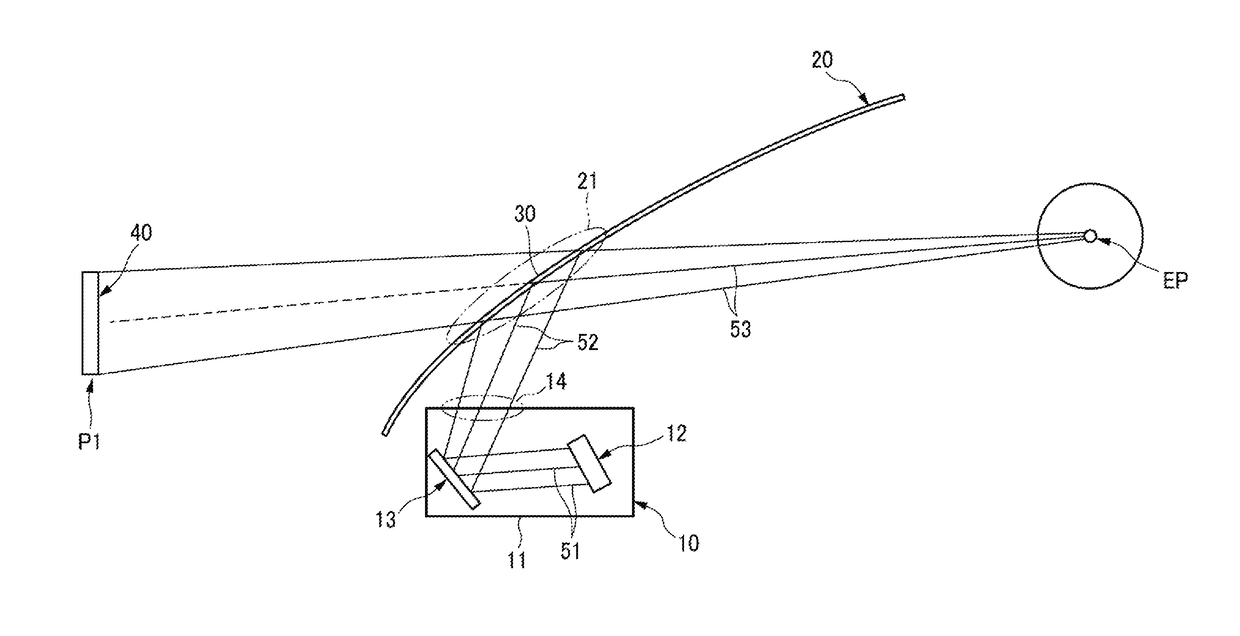
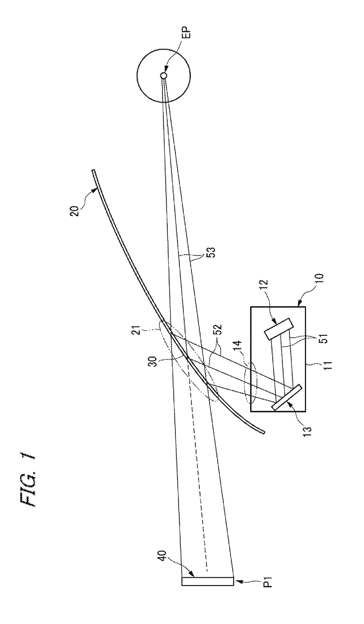
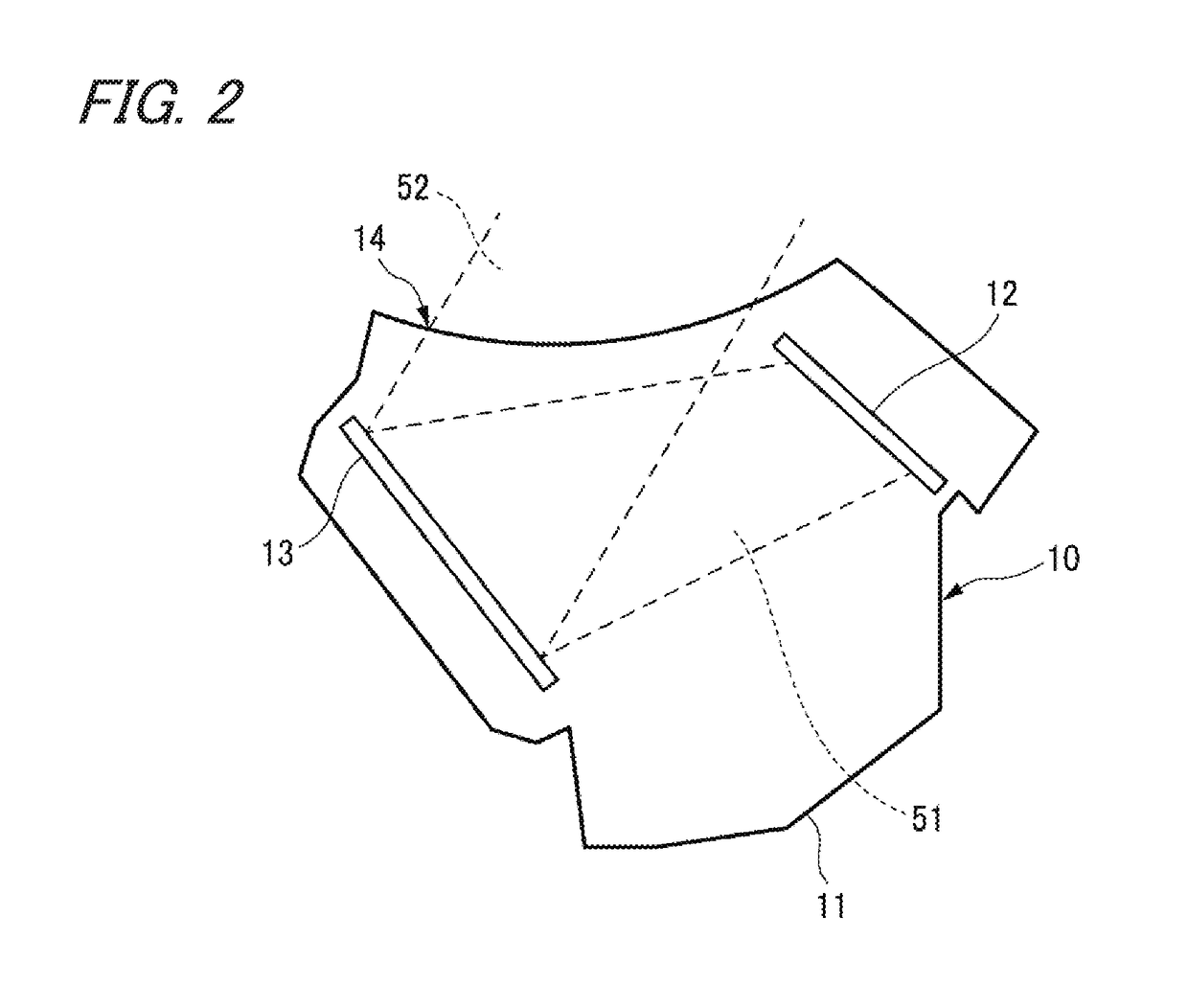
[0041]FIG. 1 shows the outline of a configuration of a display image projection system and the optical paths thereof according to an embodiment of the present invention as viewed from the side of a vehicle. Furthermore, FIG. 2 shows the internal structure of the HUD unit 10 shown in FIG. 1 and the optical paths thereof.
[0042]The display image projection system shown in FIG. 1 is intended to attain a head-up display (HUD) capable of being visually recognized by the driver on a vehicle. This display image projection system is equipped with an HUD unit 10 and a half mirror 30 with a magnifying function.
[0043]The HUD unit 10 is installed, for example, in a state of being fixed inside the dashboard ahead of the drivers seat of the vehicle. The display light emitted from the display light emitting section 14 of the HUD unit 10 passes through an optical path 52 via the opening of the dashboard and is guided to th...
second embodiment
[0092]In the above-mentioned display image projection system shown in FIG. 1, the free-curved surface Fresnel mirror 13 has the distortion correction function and the half mirror 30 with the magnifying function has the magnifying function. In a second embodiment, however, the free-curved surface Fresnel mirror 13 has a magnifying function in addition to the distortion correction function.
[0093]Hence, in the second embodiment, an image can be optically magnified by using both the free-curved surface Fresnel mirror 13 and the half mirror 30 with the magnifying function. The curvature distribution state of the Fresnel surface of the free-curved surface Fresnel mirror 13 in the second embodiment, not shown, is different from that in the first embodiment because the free-curved surface Fresnel mirror 13 is provided with the magnifying function. The function and the structure of the half mirror 30 with the magnifying function in the second embodiment are similar to those in the first embo...
third embodiment
[0096]In the above-mentioned display image projection system shown in FIG. 1, the free-curved surface Fresnel mirror 13 has the distortion correction function and the half mirror 30 with the magnifying function has the magnifying function. In a third embodiment, however, each of the free-curved surface Fresnel mirror 13 and the half mirror 30 with the magnifying function has both the distortion correction function and the magnifying function.
[0097]Hence, in the third embodiment, an image can be optically magnified and distortion correction can be carried out by using both the free-curved surface Fresnel mirror 13 and the half mirror 30 with the magnifying function. The curvature distribution state of the Fresnel surface of the free-curved surface Fresnel mirror 13 in the third embodiment, not shown, is different from that in the first embodiment because the free-curved surface Fresnel mirror 13 is provided with the magnifying function.
[0098]Furthermore, since the above-mentioned hal...
PUM
 Abstract
Description
Claims
Application Information
 - R&D
- Intellectual Property
- Life Sciences
- Materials
- Tech Scout
- Unparalleled Data Quality
- Higher Quality Content
- 60% Fewer Hallucinations
Browse by: Latest US Patents, China's latest patents, Technical Efficacy Thesaurus, Application Domain, Technology Topic, Popular Technical Reports.
© 2025 PatSnap. All rights reserved.Legal|Privacy policy|Modern Slavery Act Transparency Statement|Sitemap|About US| Contact US: help@patsnap.com