This helps you quickly interpret patents by identifying the three key elements:
Problems solved by technology
Method used
Benefits of technology
Benefits of technology
The patent describes a way to create high-quality images on electronic paper using a modified palette and a system that reduces the computational demands on the device by moving many of the rendering calculations off the device. This results in a thinner and more cost-effective display. The invention also takes advantage of cloud computing and wireless networking to make the system easier to install and upgrade.
Problems solved by technology
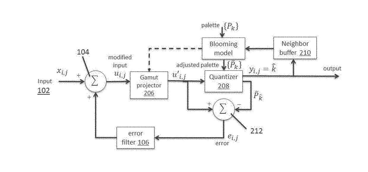
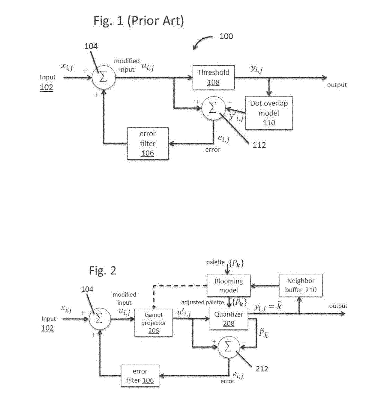
If, however, barycentric thresholding is employed, the color gamut used in step c of the method should be that of the modified palette used in step e of the method lest the barycentric thresholding give unpredictable and unstable results.
Method used
Image
Click on the blue label to locate the original text in one second.
Reading with bidirectional positioning of images and text.
Examples
example
[0231]To obtain the transformed values for the 3D LUT, an evenly spaced set of sample points (R, G, B) in the source gamut is defined, where each of these (R, G, B) triples corresponds to an equivalent triple, (R′, G′, B′), in the output gamut. To find the relationship between (R, G, B) and (R′, G′, B′) at points other than the sampling points, i.e. “arbitrary points”, interpolation may be employed, preferably tetrahedral interpolation as described in greater detail below.
[0232]For example, referring to FIG. 12, the input RGB color space is conceptually arranged in the form of a cube 14, and the set of points (R, G, B) (15a-h) lie at the vertices of a subcube (16); each (R, G, B) value (15a-h) has a corresponding (R′ G′ B′) value in the output gamut. To find an output gamut value (R′, G′, B′) for an arbitrary input gamut pixel value (R G B), as illustrated by the blue circle (17), we simply interpolate between the vertices (15a-h) of the subcube (16). In this way we, can find an (R′...
PUM
Abstract
A system for rendering color images on an electro-optic display when the electro-optic display has a color gamut with a limited palette of primary colors, and / or the gamut is poorly structured (i.e., not a spheroid or obloid). The system uses an iterative process to identify the best color for a given pixel from a palette that is modified to diffuse the color error over the entire electro-optic display. The system additionally accounts for variations in color that are caused by cross-talk between nearby pixels.
Application Information
Patent Timeline
Application Date:The date an application was filed.
Publication Date:The date a patent or application was officially published.
First Publication Date:The earliest publication date of a patent with the same application number.
Issue Date:Publication date of the patent grant document.
PCT Entry Date:The Entry date of PCT National Phase.
Estimated Expiry Date:The statutory expiry date of a patent right according to the Patent Law, and it is the longest term of protection that the patent right can achieve without the termination of the patent right due to other reasons(Term extension factor has been taken into account ).
Invalid Date:Actual expiry date is based on effective date or publication date of legal transaction data of invalid patent.

