Wire-wound fuse resistor and method for manufacturing same

a wire-wound resistor and fuse technology, which is applied in the manufacture of fuse devices, resistive element windings, electrical devices, etc., can solve the problems of surge resistance, soldering points, and certain failure rates of wire-wound resistors

Active Publication Date: 2018-09-06
FIRST RESISTOR & CONDENSER
View PDF0 Cites 12 Cited by
  • Summary
  • Abstract
  • Description
  • Claims
  • Application Information

AI Technical Summary

Problems solved by technology

When the transient energy of a surge wave is more than 100 watts, the surge loosens a certain proportion of the wound wires at the soldering points, which affects the surge resistance.
Therefore, a surge event may loosen the soldering points and a certain failure rate of the soldering points of a wire-wound resistor may ensue.
The procedure of glowing red may burn and destroy circuits and other components, and thus the effect of circuit protection is affected.

Method used


Image

  • Wire-wound fuse resistor and method for manufacturing same
  • Wire-wound fuse resistor and method for manufacturing same
  • Wire-wound fuse resistor and method for manufacturing same

Examples


Embodiment Construction

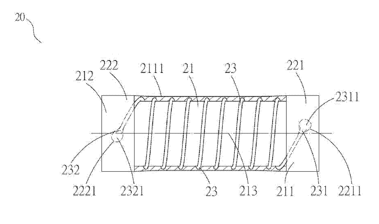
[0068]As shown in FIG. 3A, FIG. 3B, FIG. 4A and FIG. 4B, according to the first example of the present invention (the MELF type of wire-wound resistor), the present invention provided a surge-resistant wire-wound resistor 20, comprising:[0069]a ceramic rod 21 which had a first end 211 and a second end 212;[0070]one or more than one wound metal wire 23 which had a wire head 231 and a wire tail 232 and was helically wound around the ceramic rod from the first end 211 to the second end 212;[0071]a first cap 221 and a second cap 222 which were respectively disposed along an axis of the ceramic rod 21 and extending outwardly from the first end 211 and the second end 212, wherein the wire head 231 and the wire tail 232 were respectively soldered on the surfaces of the first cap 221 and the second cap 222 at the first cap 221 and the second cap 222, and the first cap 221 and the second cap 222 were respectively electroplated with a first cap electroplated layer 2211 on the surface of the f...


PUM


Abstract

The present invention relates to a wire-wound fuse resistor, which has: an insulating rod which has a first end and a second end; one metal wire having a wire head and a wire tail, being helically wound around the insulating rod from the first end to the second end, and being cut at a middle portion thereof to form a first winding wire and a second winding wire, which are separated from each other; a connection part disposed at the cut portion for electrical connection between the first winding wire and the second winding wire, in which the melting temperature of the connection part is lower than that of the one wound metal wire, wherein the connection part is cut off depending on a predetermined melting temperature or melting speed of the wire-wound fuse resistor.

Description

CROSS REFERENCE TO RELATED APPLICATIONS[0001]This application is a Continuation-in-Part application of the pending U.S. patent application Ser. No. 15 / 108,570 filed on Jun. 27, 2016 which is a U.S. National Stage Application of PCT / CN2014 / 070761 filed Jan. 17, 2014, all of which is hereby incorporated by reference in their entirety. This application also claims priority to PCT Patent Application No. PCT / CN2017 / 090733 filed on Jun. 29, 2017, which is also incorporated by reference in its entirety. Although incorporated by reference in their entirety, no arguments or disclaimers made in the parent application apply to this Continuation-in-Part application. Any disclaimer that may have occurred during the prosecution of the above-referenced application(s) is hereby expressly rescinded. Consequently, the Patent Office is asked to review the new set of claims in view of the entire prior art of record and any search that the Office deems appropriate.FIELD OF THE INVENTION[0002]The inventi...

Claims


Application Information

Patent Timeline
Patent Type & Authority Applications(United States)
IPC IPC(8): H01H85/048H01H85/02H01C3/20H01C17/04H01H69/02H01C1/14
CPCH01C17/04H01H69/02H01C1/14H01H85/048H01H85/0241H01C3/20H01C3/14H01C17/02H01H85/08H01H85/12
Inventor LEE, SHANG-YO
Owner FIRST RESISTOR & CONDENSER
Why Eureka
Try Eureka