
Intraoral phototherapy devices

Active Publication Date: 2018-09-13
LUMITEX
View PDF10 Cites 11 Cited by
  • Summary
  • Abstract
  • Description
  • Claims
  • Application Information

AI Technical Summary

Benefits of technology

The present invention is related to intraoral phototherapy devices that can better control the amount of light therapy administered. The invention uses side light channels to evenly distribute light to targeted areas in the mouth. The device also includes integral top and bottom flaps to stabilize it during treatment and prevent it from rotating in the mouth. These flaps help to improve the accuracy and effectiveness of phototherapy treatments.

Problems solved by technology

Oral Mucositis is one of the most common and highly significant toxicities of cancer therapy.
Barriers to the acceptance of low level laser therapy include the cost of laser equipment and the labor intensiveness.
Additionally, there are problems with interoperator variability and the need for specialized training.
Also patients receiving this form of treatment are required to hold their mouths open for long periods of time which is uncomfortable and becomes extremely painful as the Mucositis progresses.
The main disadvantages of using LED arrays for administering phototherapy treatment is that they lack dose control because they must transilluminate cheek tissue and have difficulty reaching all regions of the oral cavity, including the tonsillar and palatal regions which are highly susceptible to OM.
Also variability in tissue thickness between different buccal regions and different patients makes it impossible to accurately monitor and control the dose of light administered to the mucosa.

Method used


Image

  • Intraoral phototherapy devices
  • Intraoral phototherapy devices
  • Intraoral phototherapy devices

Examples


Embodiment Construction

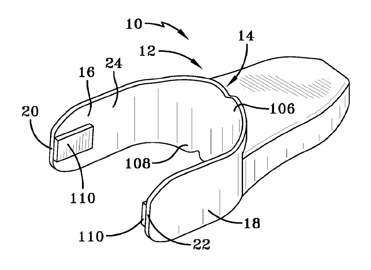
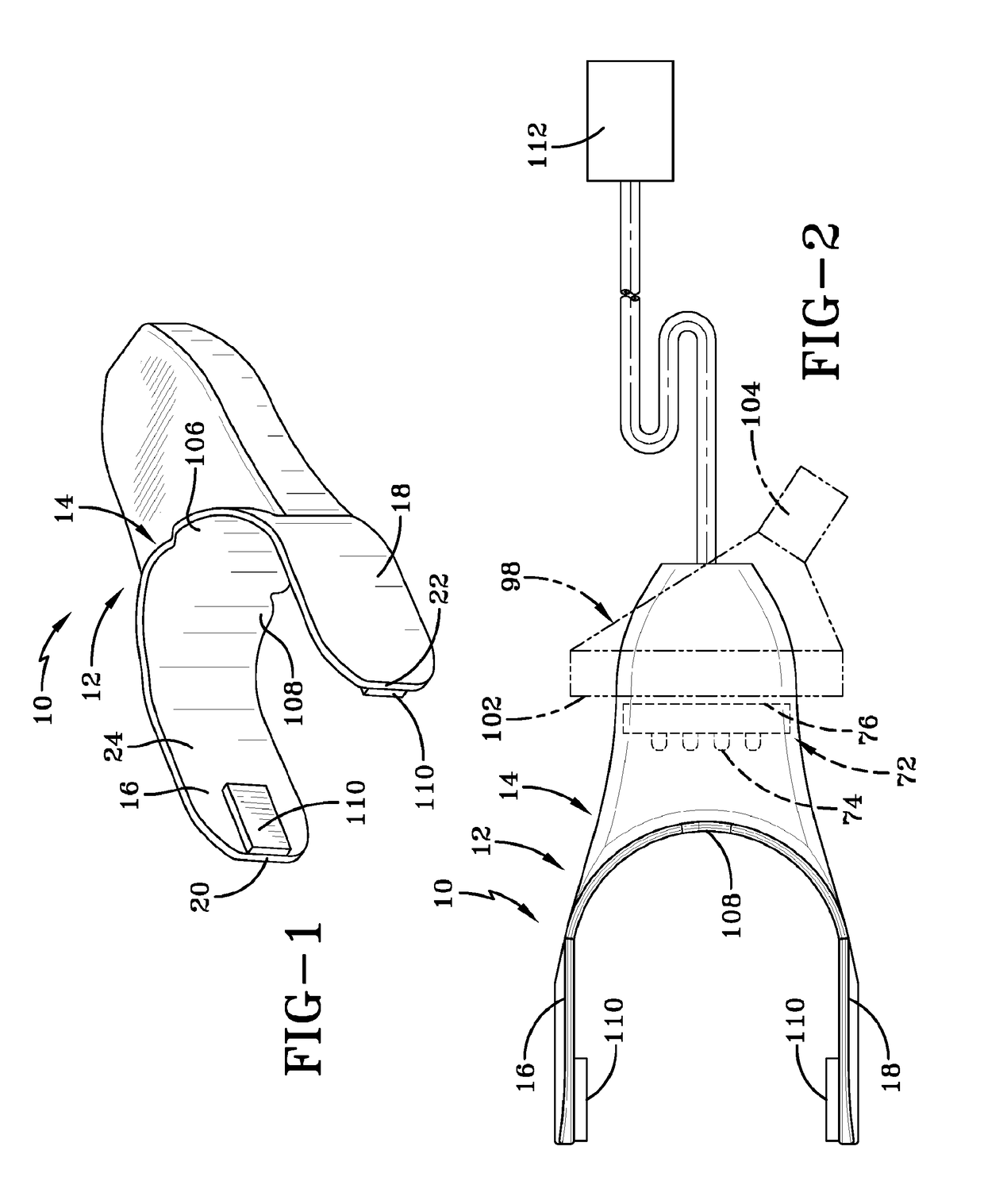
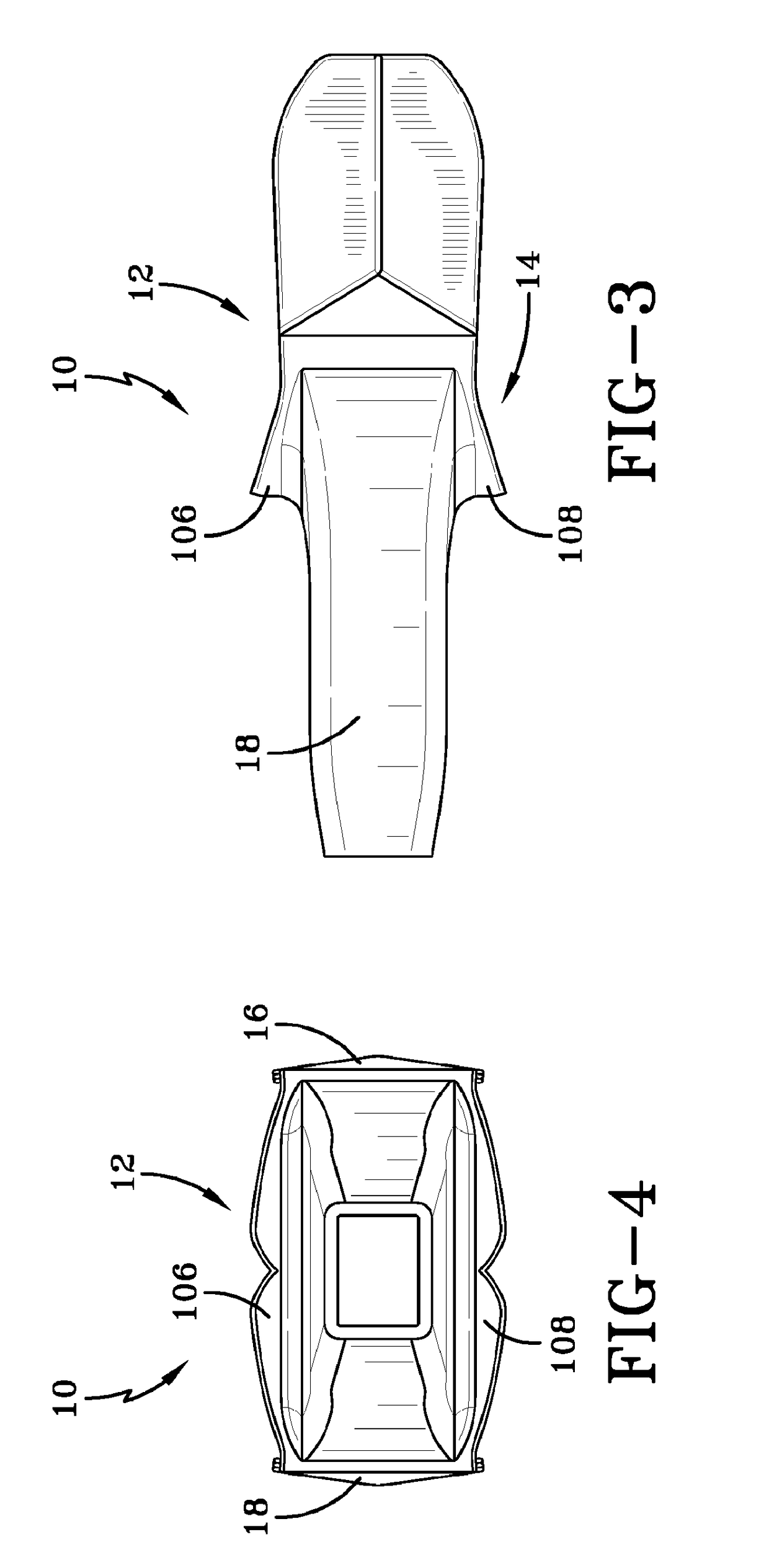
[0044]Referring now more particularly to the drawings, wherein the same reference numbers are used to designate like parts, and initially to FIGS. 1-4, there is shown an embodiment of an intraoral phototherapy device 10 comprising a light guide 12 that receives light from an external light source. In all of the embodiments disclosed herein, the light guide 12 comprises a main body portion 14 made of an optically transparent soft flexible biocompatible polymeric material such as silicone. However, the body portion 14 may be made of other optically clear biocompatible soft polymeric materials as well including but not limited to different formulations of polycarbonate, polymethyl methacrylate, polystyrene, nylon, acrylonitrile butadiene styrene, polyolefin, or other biocompatible thermoplastic elastomer formulations.

[0045]The intraoral phototherapy device may be used in a number of applications, several examples of which include oral mucositis, acute necrotizing ulcerative gingivitis ...


PUM


Abstract

Intraoral phototherapy devices receive light from an associated light source and propagate the light into an oral cavity of a patient. The device comprises a light guide that receives light from an external light source. The light guide comprises a main body portion made of an optically transparent soft flexible biocompatible polymeric material sized and shaped to conform to contours of the oral cavity when inserted therein to direct the light to targeted regions of the oral cavity. The main body portion comprises a pair of spaced apart side wings sized and shaped to be received between a patient's teeth and cheeks on opposite sates of the oral cavity and a center flap intermediate the side wings hr transmitting and directing the light to targeted regions of the oral cavity. A controller delivers light to the light guide in a controlled manner.

Description

RELATED APPLICATIONS[0001]This application claims the benefit of U.S. 62 / 216,825 filed Sep. 10, 2015. Which is herein incorporated by reference in its entirety.TECHNICAL FIELD[0002]This invention relates generally to intraoral phototherapy devices for receiving light from an associated light source and propagating the light into the oral cavity of a patient by total internal reflection and emission for phototherapy treatment of targeted regions of the oral cavity.BACKGROUND[0003]Currently there are two known methods for administering phototherapy for the treatment of various phototherapy treatment conditions of the mouth including, but not limited to Oral Mucositis (OM), low level laser therapy and light emitting diode (LED) arrays. Oral Mucositis is one of the most common and highly significant toxicities of cancer therapy.[0004]Barriers to the acceptance of low level laser therapy include the cost of laser equipment and the labor intensiveness. Additionally, there are problems wit...

Claims


Application Information

Patent Timeline
IPC IPC(8): A61N5/06
CPCA61N5/0603A61N5/0624A61N2005/0606A61N2005/063A61B2017/00084A61N2005/0645A61B2018/00791A61N2005/005A61N2005/0626A61N2005/0651A61N2005/0666A61B2017/00035A61B2018/00839A61B2090/034
Inventor KOTHARI, VEDANGBROER, PETER W.
Owner LUMITEX
Learn More