

Near-Field Microwave Heating System and Method
a microwave heating and near-field technology, applied in the direction of antennas, waveguides, applications, etc., can solve the problems of increasing the non-uniformity of heating, difficult modeling and the inability to place workpieces in the near-field region
Active Publication Date: 2018-09-13
EXPERT TOOLING & AUTOMATION LTD
View PDF0 Cites 8 Cited by
- Summary
- Abstract
- Description
- Claims
- Application Information
AI Technical Summary
Benefits of technology
The invention is about a microwave heating system that can be used for curing materials such as adhesives or polymers using microwave energy. The system includes a microwave source, a waveguide with a launch structure, and a fixture to hold the material to be treated near the launch structure. The microwave energy is applied through the launch structure to a small portion of the material, causing it to be cured while the rest of the material remains unaffected. The system can also be used to apply microwave energy to large areas of materials using multiple layers of fiber reinforced prepreg tape. The technical effect of this invention is the ability to efficiently and accurately control the curing process using microwave energy, resulting in improved product quality and productivity.
Problems solved by technology
Avoiding the near-field region is done for several reasons:1. The workpiece is generally larger than the near-field region, so placing the part too close to the launcher will greatly increase the non-uniformity of heating.2. Modeling the electric field distribution in a large multimode cavity is relatively straightforward for the far field case, whereas modeling in the near-field region is very difficult.
However, even in this case, the workpiece cannot be placed in the near-field region where the incoming power density is extremely high because it will prevent the microwave energy from fanning out and establishing the multitude of modes responsible for creating a uniform environment in most of the cavity.
A major problem in use of carbon fiber composites for various components in an automotive assembly line is that conventional fasteners and tack welding cannot be used, so adhesive bond joints are typically used to join CFC components to CFC components and CFC components to metal components.
However, the time to cure the adhesive joint can be 15-20 minutes, which is not compatible the pace of automotive assembly line production.
A microwave oven is not practical because of the size and the fact that conventional microwave energy is not uniform and will arc with metals and with carbon fibers in CFCs.
Method used
View moreImage
Smart ImageViewing Examples

Examples
example
[0148]To demonstrate the ability to perform near-field heating in a general-purpose VFM cavity 80, in which the existing launcher is on the rear wall of the chamber, two standard waveguide H bends 82 were attached to direct power to a waveguide launch in the middle of the chamber as shown generally in FIG. 8A. A fixture 83 was constructed to support a quartz tube 84 through which process gases could be passed as shown generally in FIG. 8B.
Login to View More PUM
| Property | Measurement | Unit |
|---|---|---|
| cure temperature | aaaaa | aaaaa |
| frequency | aaaaa | aaaaa |
| frequencies | aaaaa | aaaaa |
Abstract
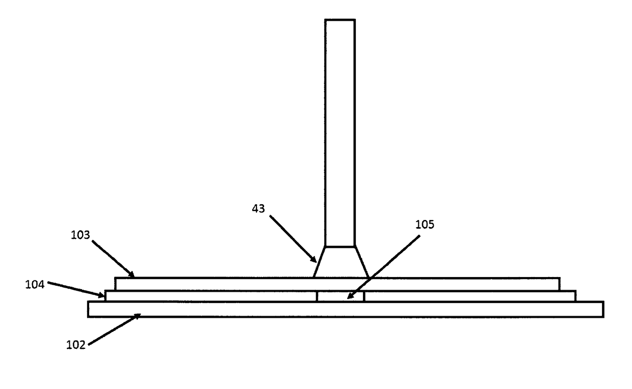
A microwave heating device includes a variable frequency microwave power supply, a waveguide launcher, and a fixture to contain a material to be heated, with the fixture located directly adjacent to the end of the launcher. All heating occurs in the near-field region. This condition may be insured by keeping the thickness of the fixture or workpiece under one wavelength (at all microwave frequencies being used). The launcher is preferably a horn or waveguide configured to apply the microwave power to a small area to perform spot curing or repair operations involving adhesives and composites. The spot curing may secure components in place for further handling, after which a thermal or oven treatment will cure the remaining adhesive to develop adequate strength for service.A related method is also disclosed.
Description
CROSS REFERENCE TO RELATED APPLICATION[0001]The present application is a continuation-in-part of U.S. patent application Ser. No. 15 / 731,881, entitled Near-Field Microwave Heating System, filed by the present inventors on Aug. 18, 2017, which further claims the benefit of Provisional Patent Application Ser. No. 62 / 497,062 filed by the present inventors on Nov. 7, 2016, the entire disclosures of which are incorporated herein by reference.BACKGROUND OF THE INVENTIONField of the Invention[0002]The invention pertains to apparatus and methods for heating materials with microwaves, and more particularly to spot-curing thermosetting materials using a near-field microwave applicator.Description of Related Art[0003]Microwave heating systems generally rely on a waveguide launcher that introduces microwave energy into an enclosed volume, referred to as a cavity. The cavity is typically metal, and the cavity walls enclose and define a volume of space in which microwave fields are established. T...
Claims
Login to View More Application Information
Patent Timeline
 Patent Type & AuthorityApplications(United States)
IPC IPC(8): B29C65/14H01P1/26H01P1/22H01P3/123B29C65/48B29C65/00B29C73/12
CPCB29C65/1425H01P1/264H01P1/222H01P3/123B29C65/4805B29C66/21B29C66/7212B29C73/12B29L2031/3005B29C73/34H01Q13/0266H01Q13/0275B29C2035/0855
InventorAHMAD, IFTIKHARHICKS, KEITH R.CARDIN, ANDREWDECAMILLIS, CLAYTON R.HAZELHURST, RICHARD C.LUCIANO, ANGELOBOOLS, ANDREW
OwnerEXPERT TOOLING & AUTOMATION LTD