Extruded control rod guide frame

a control rod and guide frame technology, applied in the direction of nuclear engineering, nuclear elements, greenhouse gas reduction, etc., can solve the problems of a large number of welds, prone to welding-induced distortion, and labor-intensive manufacturing process, and achieve the effect of reducing torsion

Active Publication Date: 2018-09-13
BWXT MPOWER INC
View PDF0 Cites 3 Cited by
  • Summary
  • Abstract
  • Description
  • Claims
  • Application Information

AI Technical Summary

Benefits of technology

[0011]In some illustrative embodiments, a method comprises: extruding at least two radial guide frame sections using a hot extrusion process; and assembling the guide frame sections to form a control rod guide frame body having a central passage of constant cross-section as a function of position along a central axis that passes through the central passage, the central passage sized and shaped to guide a traveling assembly including at least one control rod as the traveling assembly moves along the central axis. In some embo...

Problems solved by technology

In guide frames constructed from a series of plates spaced a distance apart from each other with segmented tubes inserted between the plates and then welded i...

Method used


Image

  • Extruded control rod guide frame
  • Extruded control rod guide frame
  • Extruded control rod guide frame

Examples


Embodiment Construction

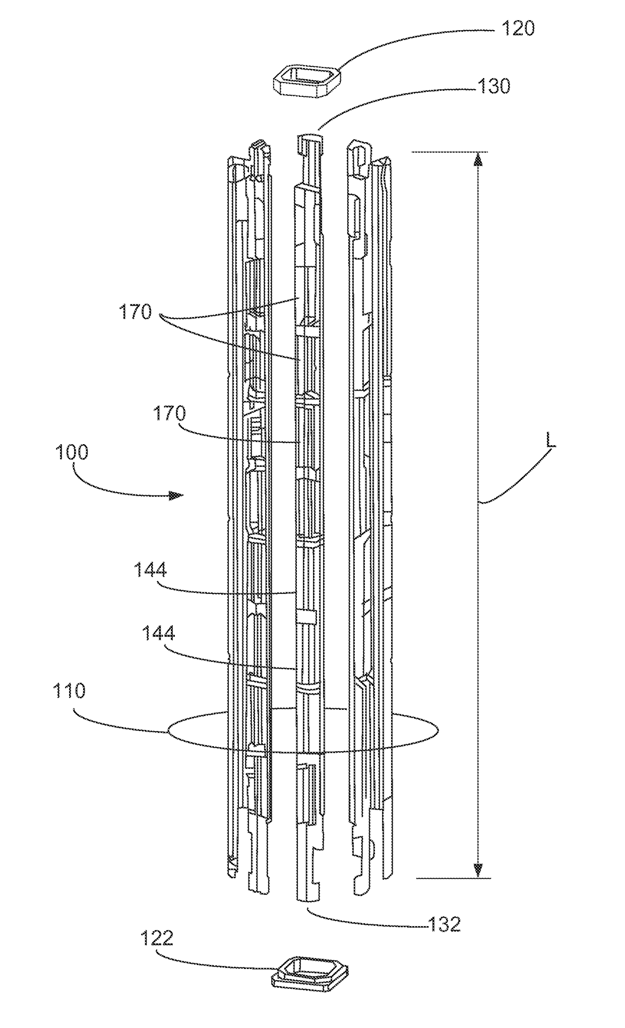
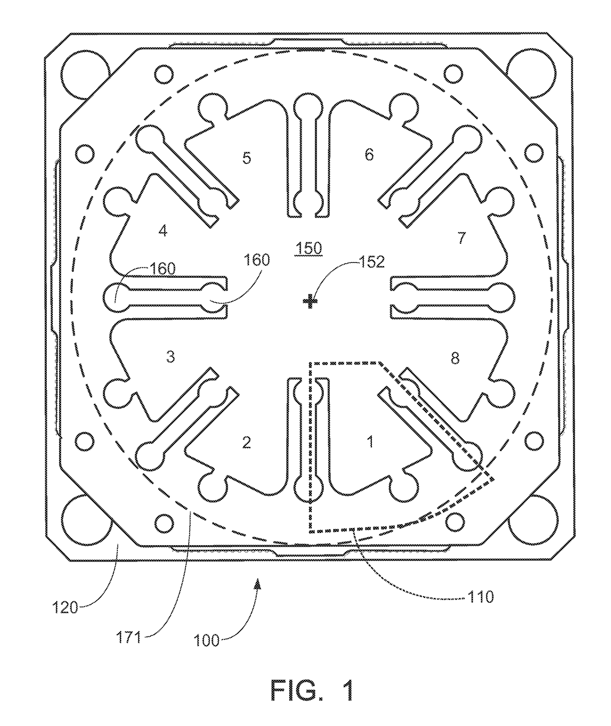
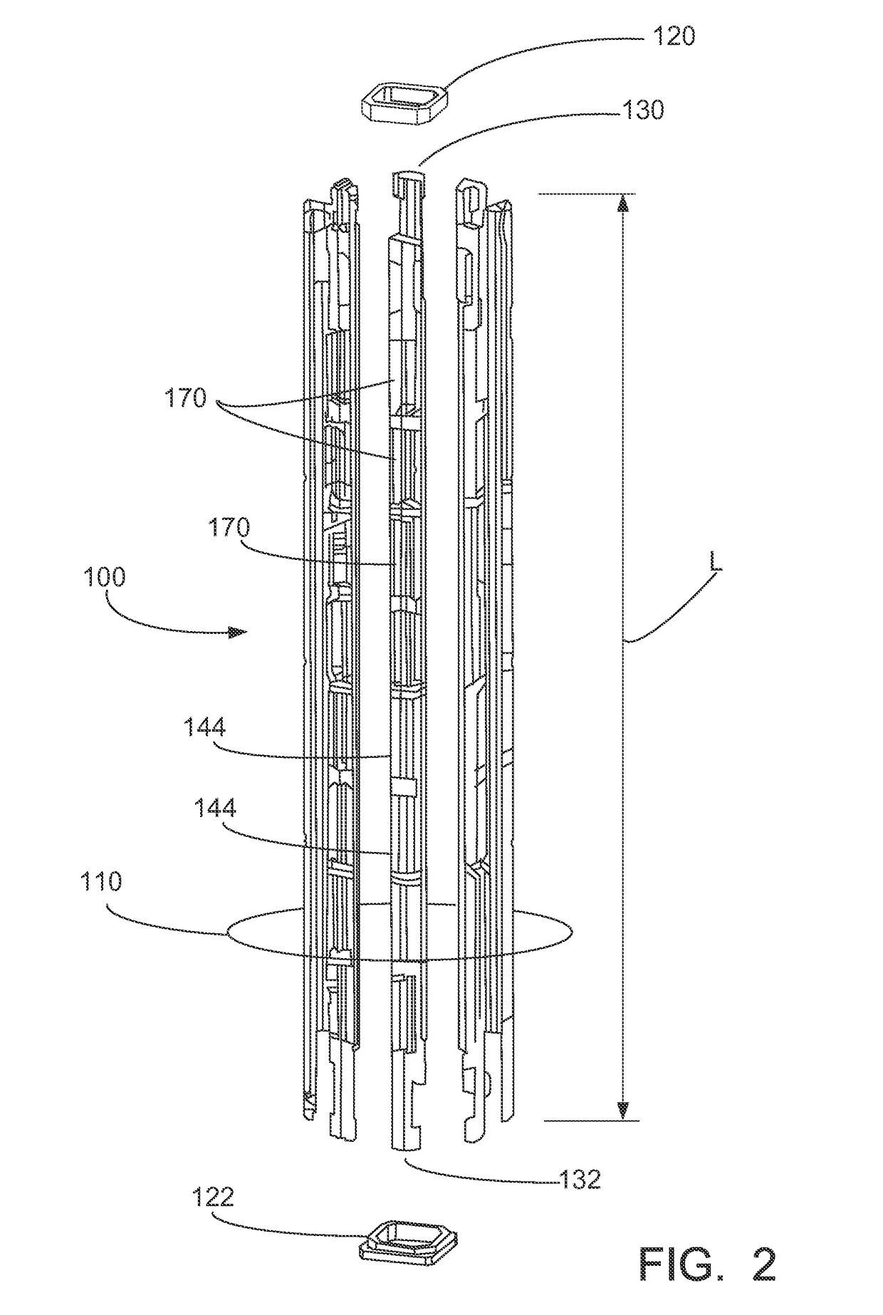
[0023]The various features of novelty which characterize the invention and methods are pointed out with particularity in the claims annexed to and forming a part of this disclosure. For a better understanding of the invention and methods, its operating advantages and specific benefits attained by its uses, reference is made to the accompanying drawings and descriptive matter in which exemplary embodiments of the invention are illustrated. These figures are merely schematic representations based on convenience and the ease of demonstrating the existing art and / or the present development, and are, therefore, not intended to indicate relative size and dimensions of the assemblies or components thereof.

[0024]Although specific terms are used in the following description for the sake of clarity, these terms are intended to refer only to the particular structure of the embodiments selected for illustration in the drawings, and are not intended to define or limit the scope of the disclosure...


PUM


Abstract

A control rod guide frame has a central passage of constant cross-section as a function of position along a central axis that passes through the central passage. The central passage is sized and shaped to guide a traveling assembly including at least one control rod as it moves along the central axis. The control rod guide frame comprises at least two radial guide frame sections secured around and defining the central passage. Each radial guide frame section may comprise an extruded radial guide frame section, which may be made of extruded steel. The central passage may include control rod guidance channels parallel the central axis and machined into the extruded radial guide frame sections. The at least two radial guide frame sections may be interchangeable. In some embodiments the at least two radial guide frame sections consist of between four and eight radial guide frame sections.

Description

[0001]This application claims the benefit of U.S. Provisional Application No. 61 / 791,877 filed Mar. 15, 2013 and titled “EXTRUDED GUIDE FRAME AND MANUFACTURING METHODS THEREOF”. U.S. Provisional Application No. 61 / 791,877 filed Mar. 15, 2013 and titled “EXTRUDED GUIDE FRAME AND MANUFACTURING METHODS THEREOF” is hereby incorporated by reference in its entirety into the specification of this application.BACKGROUND[0002]The following relates in general, to the field of nuclear power reactor arts, nuclear reaction control apparatus arts, control rod assembly arts, and related arts. More particularly, the following is directed to control rod guide frames and manufacturing methods thereof.[0003]In nuclear power plants, a nuclear reactor core comprises a fissile material having size and composition selected to support a desired nuclear fission chain reaction. To moderate the reaction, a neutron absorbing medium may be provided, such as light water (H2O) in the case of light water reactors,...

Claims


Application Information

Patent Timeline
IPC IPC(8): G21C7/08G21C7/10G21C21/18
CPCG21C3/326G21C7/12Y02E30/30
Inventor SHARGOTS, SCOTT J
Owner BWXT MPOWER INC
Why Eureka
Try Eureka