Injection Moulding Method

a technology of injection moulding and injection molding, which is applied in the field of injection moulding an article, can solve the problems that the cavity most remote from the gate may not be fully filled with molten plastics materials, and achieve the effect of reducing the l/t ratio

Active Publication Date: 2018-09-20
GR8 ENG
View PDF12 Cites 1 Cited by
  • Summary
  • Abstract
  • Description
  • Claims
  • Application Information

AI Technical Summary

Benefits of technology

[0044]Accordingly, the preferred embodiments of the present invention provides a method which can actively changes the L/T ratio of a moulded article during injection from a relatively low average L/T ratio in a first intermediate moulding cavity to a relatively high average L/T ratio in a subsequent second intermediate moulding cavity, and a ye

Problems solved by technology

However, for wall thicknesses of less than 1 mm and L/T ratios of greater than 50, even if a high injection pressure at the gat

Method used


Image

  • Injection Moulding Method
  • Injection Moulding Method
  • Injection Moulding Method

Examples


Embodiment Construction

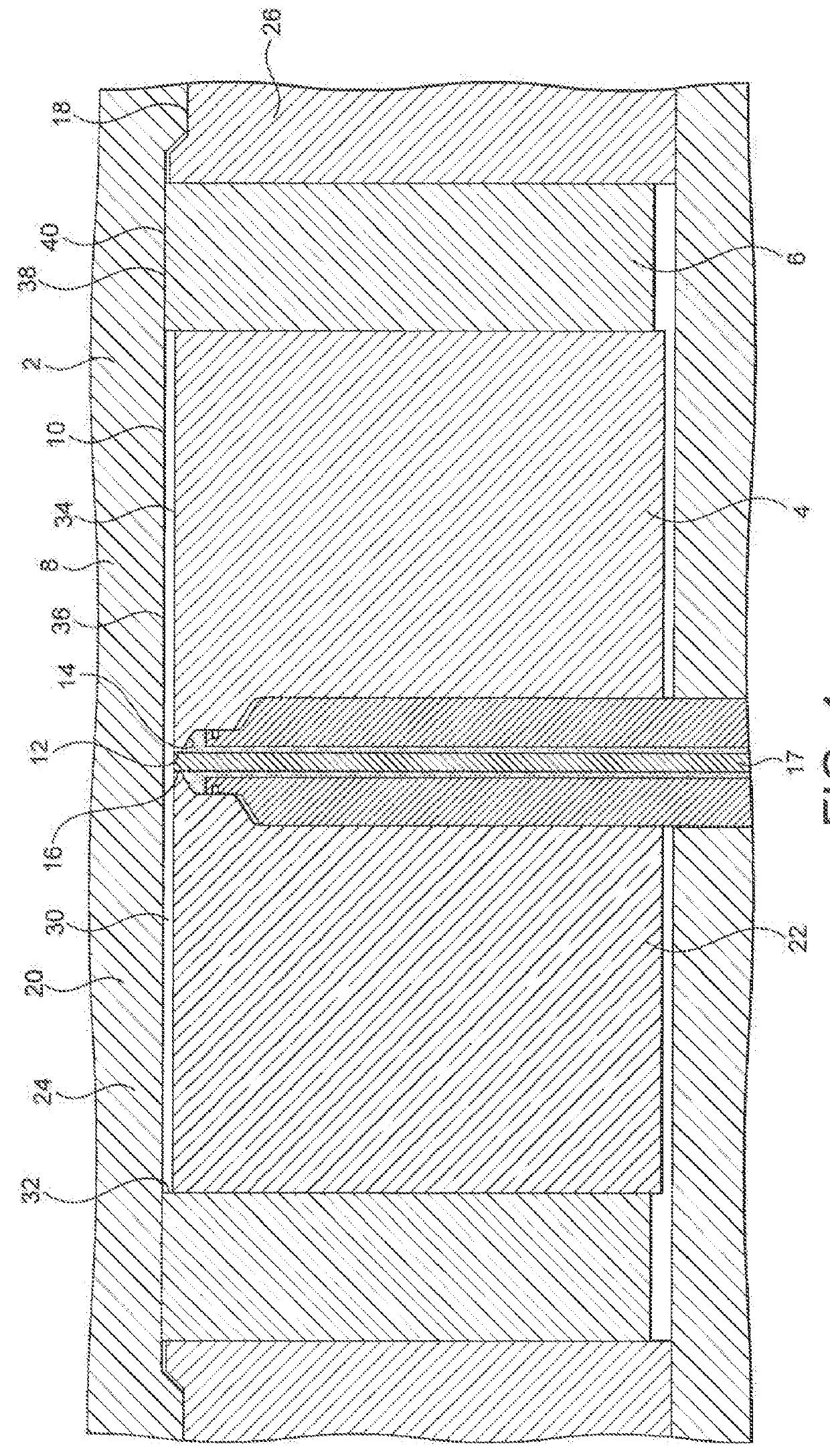
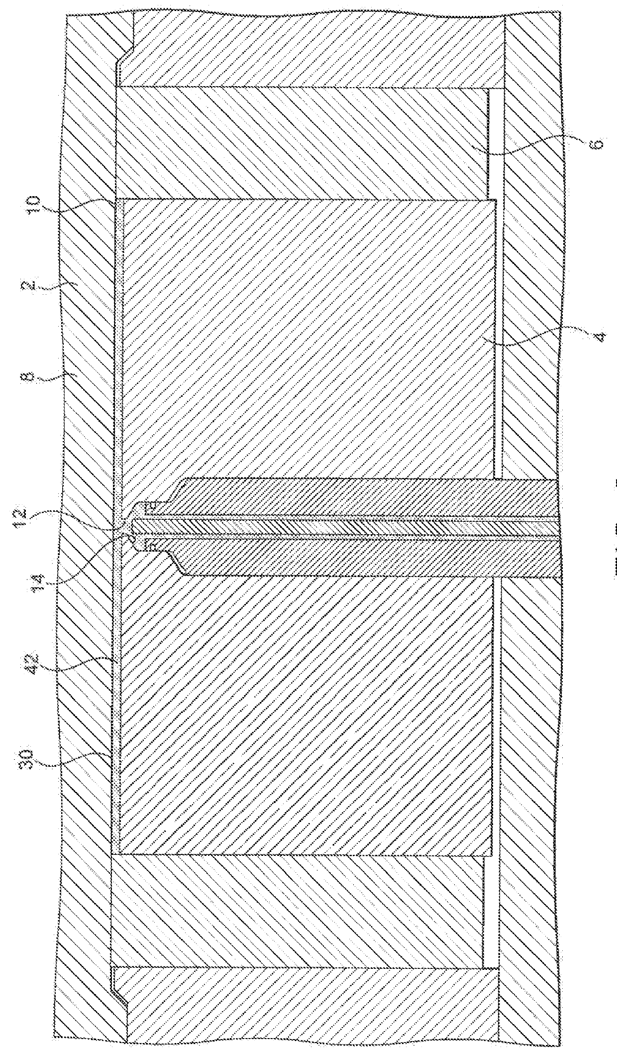
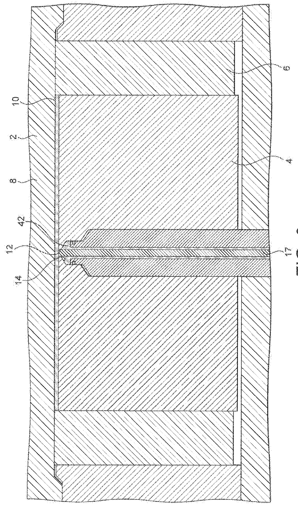
[0054]Referring to FIGS. 1 to 5, there is shown an injection mould 2 for use in a method in accordance with a first embodiment of the present invention for injection moulding a preform 100 for subsequent moulding to form a container. The preform 100 is substantially planar. The preform 100 is moulded from a thermoplastic resin material. Typically, the thermoplastic resin material comprises polyester, for example at least one polyalkylene polyester or a blend of polyalkylene polyesters. Preferably, the polyester comprises at least one polyester selected from polyethylene terephthalate, polybutylene terephthalate, polyethylene naphthalate and polybutylene naphthalate. Most preferably the polyester comprises polyethylene terephthalate (PET).

[0055]Although the embodiment shows a substantially planar preform 100, the invention can be used to mould other preform shapes, as stated above, and using other thermoplastic resins.

[0056]The injection mould 2 comprises first and second movable mou...


PUM

PropertyMeasurementUnit
Lengthaaaaaaaaaa
Lengthaaaaaaaaaa
Lengthaaaaaaaaaa

Abstract

A method of injection moulding an article, the method comprising the steps of: (a) providing an injection mould comprising a plurality of mould parts defining a mould cavity of the injection mould, the plurality of mould parts including first and second movable mould parts, the injection mould further comprising an injection inlet for injecting molten thermoplastic resin material into the mould cavity, wherein the injection inlet is located in the vicinity of the first movable mould part and the second movable mould part is remote from the injection inlet; (b) disposing the first and second movable mould parts in a first configuration so as to define a first intermediate moulding cavity, in which first configuration the first movable mould part is in a first rearward position and the second movable mould part is in a first forward position; (c) injecting molten thermoplastic resin material into the first intermediate moulding cavity through the injection inlet to fill the first intermediate moulding cavity with the molten material; (d) closing the injection inlet; (e) after commencement of the injecting step and at least partly after the closing step, moving the second movable mould part from the first forward position to a second rearward position; (f) moving the first movable mould part from the first rearward position to a second forward position; and (g) moving the second movable mould part from the second rearward position to a third forward position thereby to dispose the first and second movable mould parts in a final configuration so as to define a final moulding cavity of the injection mould filled with the molten material, the final moulding cavity defining a cavity outer surface which defines the outer shape of the article to be moulded.

Description

FIELD OF THE INVENTION[0001]The present invention relates to a method of injection moulding an article. In particular, the present invention relates to the injection moulding of preforms for containers from thermoplastic resin material.BACKGROUND[0002]Injection moulding of articles from plastics materials, in particular thermoplastic polymers, is well known in the art. In particular, the injection moulding of containers, and preforms for containers, from plastics material is conventional in the art.[0003]It is often desired to injection mould plastics containers having a small wall thickness, for example to reduce material costs. When it is necessary to injection mould an article, such as a container preform, having a high L / T ratio (where L is the flow length of the molten plastics material from the injection gate and T is the wall thickness), a high injection pressure at the gate is needed to ensure that the mould cavity is filled with the molten plastics material. The gate acts t...

Claims


Application Information

Patent Timeline
IPC IPC(8): B29C45/56B29C51/02
CPCB29C45/561B29C51/02B29C2045/2693B29C2045/5625B29C2045/564B29C2045/569B29K2105/256B29L2031/712B29K2067/003B29C45/56B29B11/08
Inventor CLARKE, PETER REGINALD
Owner GR8 ENG
Why Eureka
Try Eureka