

Suspension device
- Summary
- Abstract
- Description
- Claims
- Application Information
AI Technical Summary
Benefits of technology
Problems solved by technology
Method used
Image

Examples
first embodiment
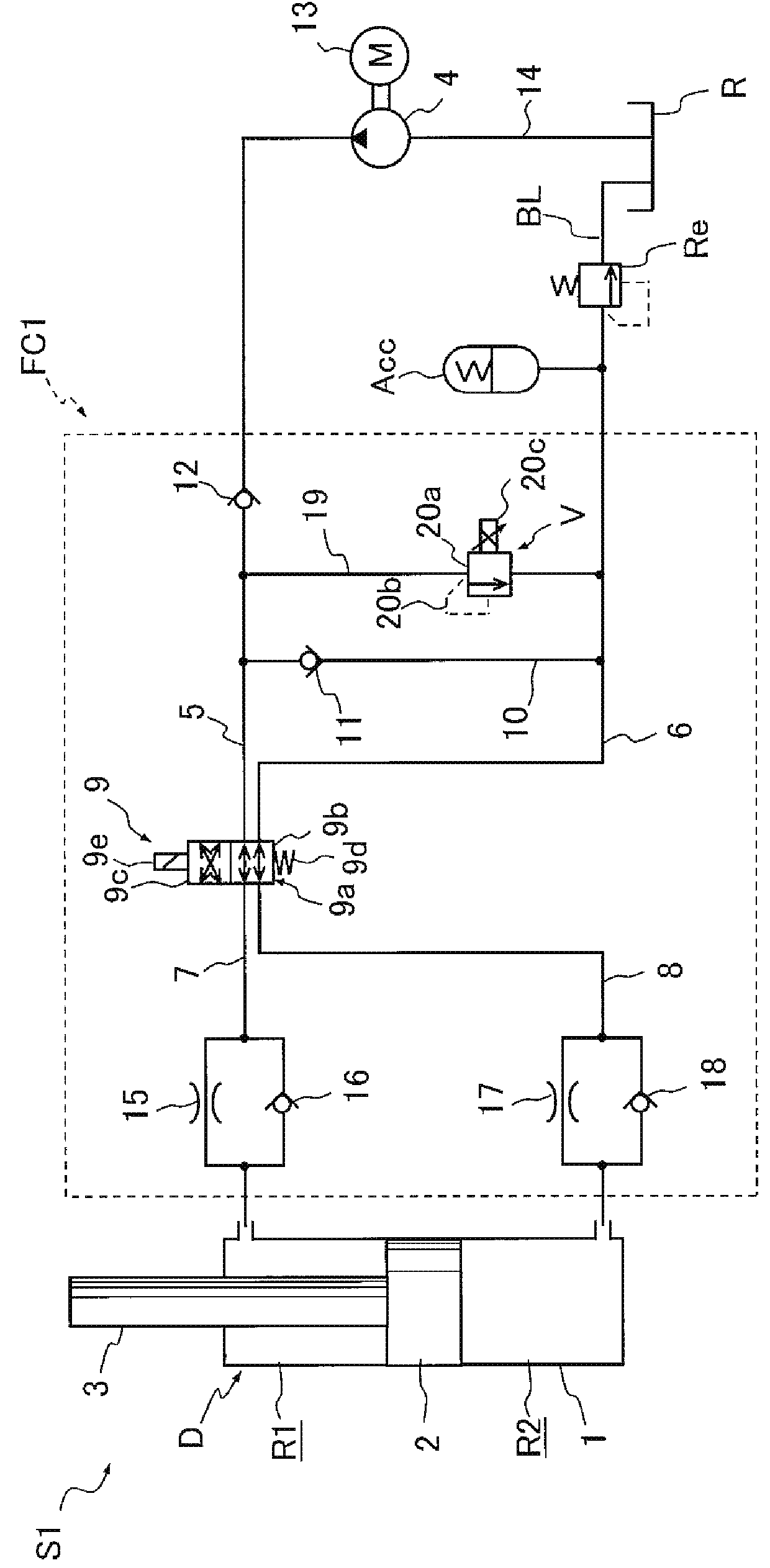
[0021]The following describes a suspension device S1 according to the first embodiment of the present invention with reference to the drawings. First, the following describes a suspension device S as a basic configuration of the suspension device S1.
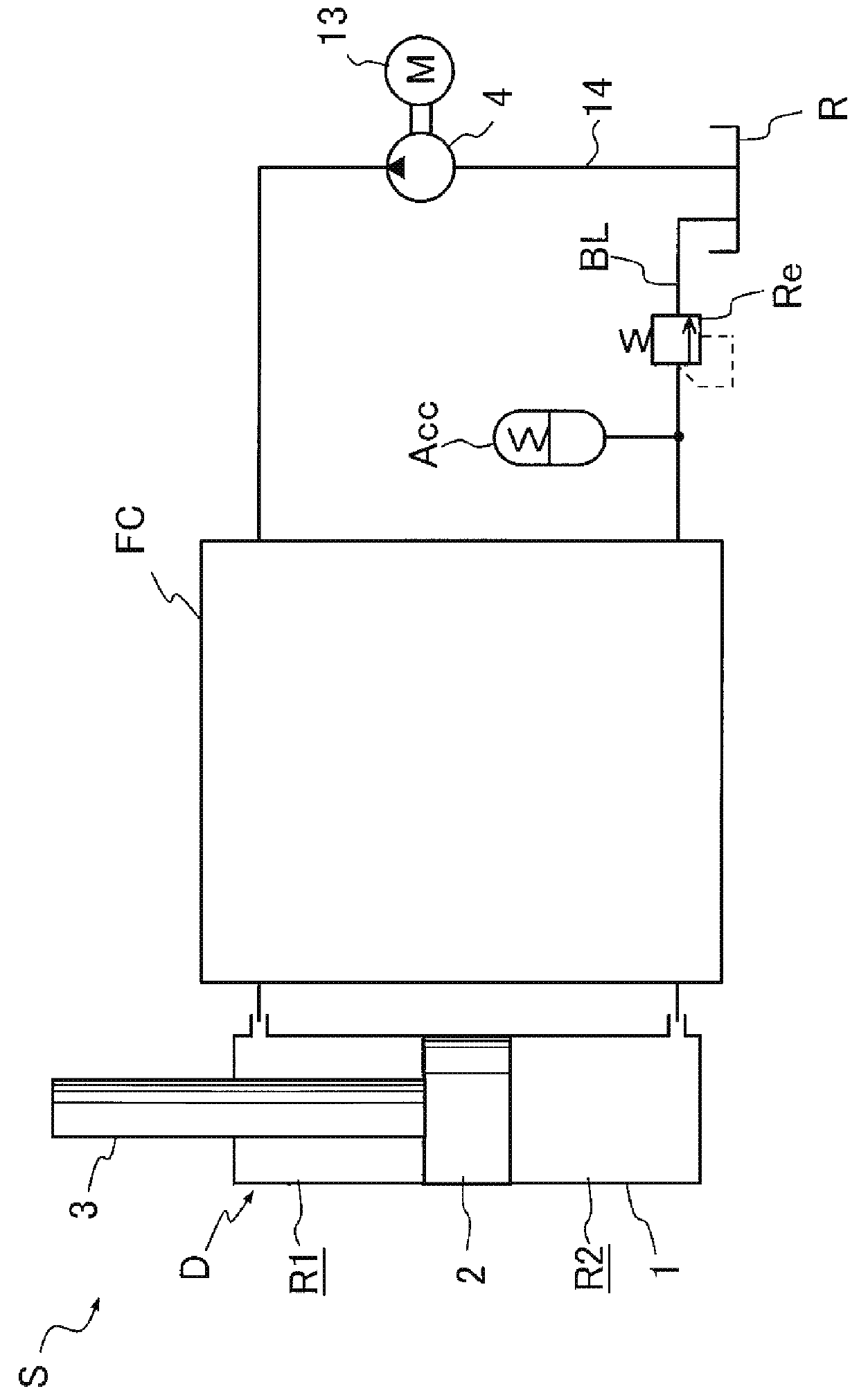
[0022]As illustrated in FIG. 1, the suspension device S includes a damper D, which includes a cylinder 1 and a piston 2, a pump 4, an accumulator Acc, a hydraulic pressure circuit FC, a reservoir R, which is connected to a suction side of the pump 4, a blow flow passage BL, which connects the accumulator Acc to the reservoir R, and a relief valve Re, which is disposed in the blow flow passage BL. The piston 2 is movably inserted into the cylinder 1 to partition the inside of the cylinder 1 into an extension-side chamber R1 and a contraction-side chamber R2. The hydraulic pressure circuit FC is disposed between the pump 4 and the accumulator Acc, and the damper D; and can adjust a thrust of the damper D.
[0023]The damper D includes a rod 3...
second embodiment
[0088]The following describes a suspension device according to the second embodiment (another exemplary configuration) including a specific hydraulic pressure circuit. A suspension device S2 according to the second embodiment includes a hydraulic pressure circuit FC2 illustrated in FIG. 7.
[0089]As illustrated in FIG. 7, the hydraulic pressure circuit FC2 differs from the hydraulic pressure circuit FC1, which controls the pressures of the extension-side chamber R1 and the contraction-side chamber R2 by the control valve V and the switching valve 9, in that a differential pressure control valve DP1 with four ports and three positions is provided between the supply passage 5, the discharge passage 6, the extension-side passage 7, and the contraction-side passage 8. Specifically, the hydraulic pressure circuit FC2 includes the differential pressure control valve DP1 at the position where the switching valve 9 is disposed instead of dispensing with the control passage 19, the control val...
third embodiment
[0131]The following describes a suspension device according to the third embodiment (another exemplary configuration) including a specific hydraulic pressure circuit. A suspension device S3 according to the third embodiment includes a hydraulic pressure circuit FC3 illustrated in FIG. 11.
[0132]As illustrated in FIG. 11, the hydraulic pressure circuit FC3 differs from the hydraulic pressure circuit FC2 in that the differential pressure control valve DP1 of the hydraulic pressure circuit FC2 is configured as a differential pressure control valve DP2 with four ports and four positions. Other configurations of the hydraulic pressure circuit FC3 are similar to those of the hydraulic pressure circuit FC2 and therefore the identical reference numerals are assigned for the identical members for omitting the detailed explanation.
[0133]The differential pressure control valve DP2 includes four ports, an A-port a2 connected to the extension-side passage 7, a B-port b2 connected to the contracti...
PUM
 Abstract
Description
Claims
Application Information