Catheter with deformable distal electrode

a distal electrode and catheter technology, applied in the field of ep catheters, can solve the problems of difficult creation of transmural lesions and undesirable steam pops, and achieve the effects of increasing the french size of the catheter, and facilitating the formation of transmural lesions

Active Publication Date: 2018-09-27
BIOSENSE WEBSTER (ISRAEL) LTD
View PDF8 Cites 4 Cited by
  • Summary
  • Abstract
  • Description
  • Claims
  • Application Information

AI Technical Summary

Benefits of technology

[0008]The present invention is directed to a catheter probe configured with a capability to present a larger tissue contact area or “footprint” for larger, deeper lesions, without increasing the french size of the catheter, especially its distal section. In some embodiments, the catheter probe includes a flexible elongated shaft and a distal section having a distal tip end, and an elastically deformable electrode configured to adopt a neutral configuration and a tissue contact configuration. The deformable electrode comprising a hollow porous tube with a distal portion having a closed distal end, and a proximal portion defining an opening to an interior of the tube, where the distal tip end is received in the tube through the opening and the distal section is generally surrounded by tube, with the proximal portion being affixed to an outer surface of the distal section. Advantageously, the closed distal end of the tube is spaced apart from the distal tip end so as to allow the distal portion to deform and expand to provide a larger tissue contact area.

Problems solved by technology

In certain regions of the heart, for example, in the ventricles where tissue is thicker, the creation of transmural lesions can be challenging.
Deep lesions typically require higher RF energy but higher RF energy can lead to undesirable steam pops.

Method used


Image

  • Catheter with deformable distal electrode
  • Catheter with deformable distal electrode
  • Catheter with deformable distal electrode

Examples


Embodiment Construction

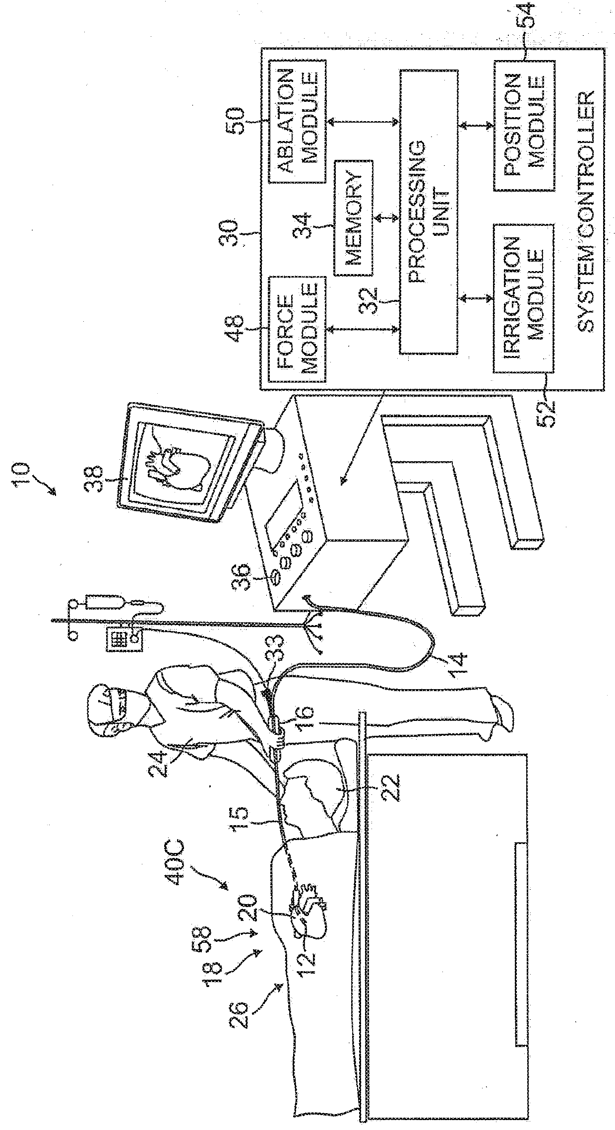
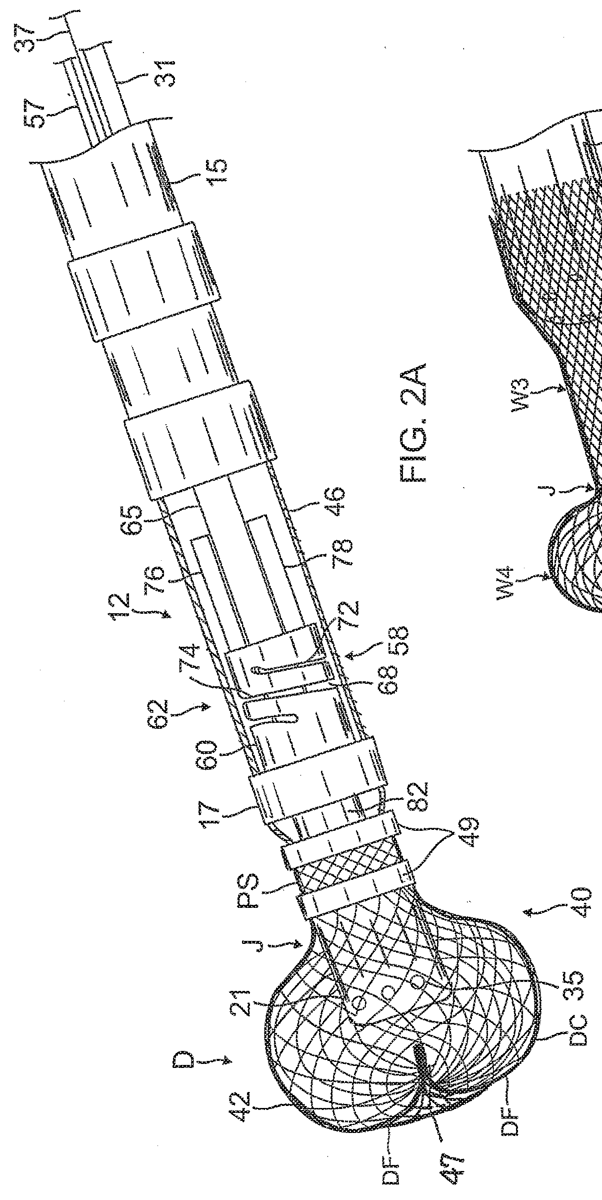
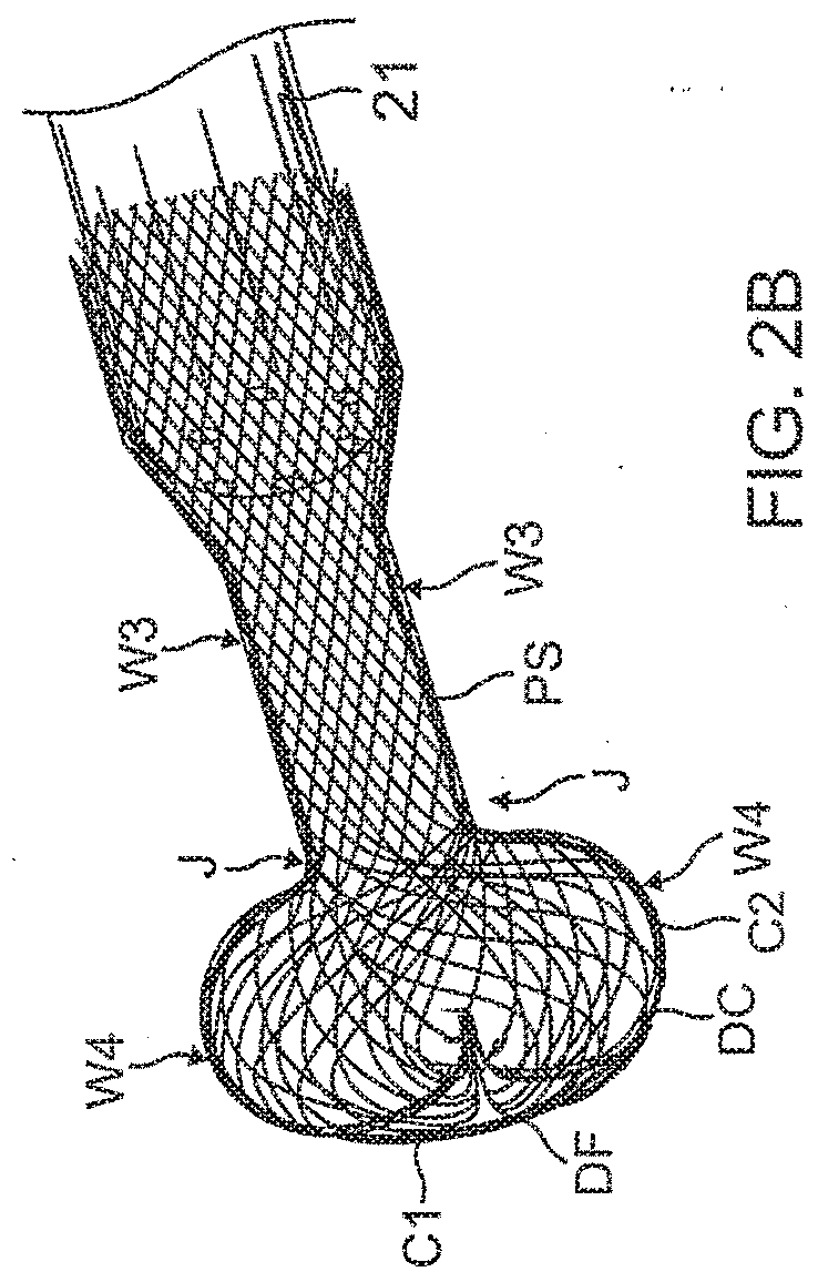
[0038]Reference is now made to FIG. 1, which is a schematic, pictorial illustration of a catheter probe ablating system 10, and to FIG. 2A which illustrates a distal section 12 of a catheter probe 14 used in the system, according to embodiments of the present invention. In system 10, probe 14 comprises an elongated shaft 15 supporting the distal section 12 and the distal section 12 and a portion of the shaft 15 are inserted into a vasculature of a subject 22, for example, a chamber of a heart 20. The probe is used by an operator 24 of system 10, during a procedure which typically includes performing ablation of body tissue 26. The distal section 12 advantageously includes a deformable electrode 40.

[0039]In some embodiments, for example, for intracardiac procedure, the shaft 15 and the distal section 12 have a very small outer diameter, typically of the order of 2-3 mm. Therefore, all of the internal components of catheter probe 14, are also made as small and thin as possible and are...


PUM


Abstract

A catheter probe configured with a capability to present a larger tissue contact area or “footprint” for larger, deeper lesions, without increasing the french size of the catheter, especially its distal section, includes an elastically deformable electrode configured to adopt a neutral configuration and a tissue contact configuration. The deformable electrode comprising a hollow porous tube with a distal portion having a closed distal end, and a proximal portion defining an opening to an interior of the tube, where the distal tip end is received in the tube through the opening and the distal section is generally surrounded by tube, with the proximal portion being affixed to an outer surface of the distal section. In some embodiments, the closed distal end is shaped with a bulbous portion that can spread and widen to provide a larger surface contact area.

Description

FIELD OF INVENTION[0001]This invention relates to electrophysiologic (EP) catheters, in particular, deflectable EP catheters for RF ablation.BACKGROUND[0002]Electrode catheters have been in common use in medical practice for many years. They are used to stimulate and map electrical activity in the heart and to ablate sites of aberrant electrical activity.[0003]In use, the electrode catheter is inserted into a major vein or artery, e.g., femoral vein, and then guided into the chamber of the heart which is of concern. In some medical procedures, energy is imparted to body tissue locally, in a concentrated dose, and it is desirable to cool the treatment area in order to reduce collateral tissue damage. For example, cardiac ablation therapy is used to treat arrhythmias by heating tissue with radio-frequency (RF) electrical energy to create non-conducting lesions in the myocardium. It has been found that cooling the area of the ablation site reduces tissue charring and thrombus formation...

Claims


Application Information

Patent Timeline
Patent Type & Authority Applications(United States)
IPC IPC(8): A61B18/14A61M25/00A61B5/296
CPCA61B18/1492A61M25/008A61M25/0043A61B2018/1465A61B2018/00988A61B2018/00577A61M2205/0216A61B2018/0022A61B2018/00023A61B2018/00744A61B2018/00714A61M2205/0233A61B2018/00351A61B2018/00839A61B2018/00595A61B2018/00065A61B2018/00077A61B2018/00267A61B2018/00357A61B2218/002A61B2090/064A61B2090/067A61B90/37A61B2034/2051A61B2090/3958A61M2025/0081A61M25/0069A61B2034/2046
Inventor BASU, SHUBHAYUSOLIS, MARIO A.
Owner BIOSENSE WEBSTER (ISRAEL) LTD
Why Eureka
Try Eureka