Pressure reduction-absorbing bottle

a technology of pressure reduction and absorbing bottle, which is applied in the direction of rigid containers, packaging, transportation and packaging, etc., can solve the problems of high potential safety hazards, and the appearance of the pressure reduction-absorbing bottle is likely to deteriorate, so as to achieve the effect of increasing the time of contents

Active Publication Date: 2018-09-27
YOSHINO KOGYOSHO CO LTD
View PDF18 Cites 1 Cited by
  • Summary
  • Abstract
  • Description
  • Claims
  • Application Information

AI Technical Summary

Benefits of technology

[0015]In this case, in the vertical cross-sectional view in the bottle axial direction, the length of the curved portion is longer than the length of the inclined portion. For this reason, the movable wall portion can be rotationally moved downward about the connection portion between the inclined portion and the upper end portion of the rising circumferential wall portion while deformation of the inclined portion is minimized at the time of filling of the contents. Therefore, an amount of displacement toward the side below the movable wall portion at the time of filling of contents can be effectively increased.
[0016]According to the present invention, a movable wall portion can be rotationally moved evenly upward over the entire circumference when a pressure in the bottle becomes negative after sealing is applied and a pressure-reduction absorbing capacity can be increased without deteriorating ground-contact stability at the time of filling of contents.

Problems solved by technology

In this case, the appearance of the pressure reduction-absorbing bottle is likely to deteriorate and a height position of a liquid surface is likely to be different for each of pressure reduction-absorbing bottles despite being filled with the same amount of contents.
For this reason, for example, ground-contact stability is likely to deteriorate due to the occurrence of unnecessary deformation of the grounding portion such as large local deformation of part of the grounding portion.

Method used


Image

  • Pressure reduction-absorbing bottle
  • Pressure reduction-absorbing bottle
  • Pressure reduction-absorbing bottle

Examples


an embodiment

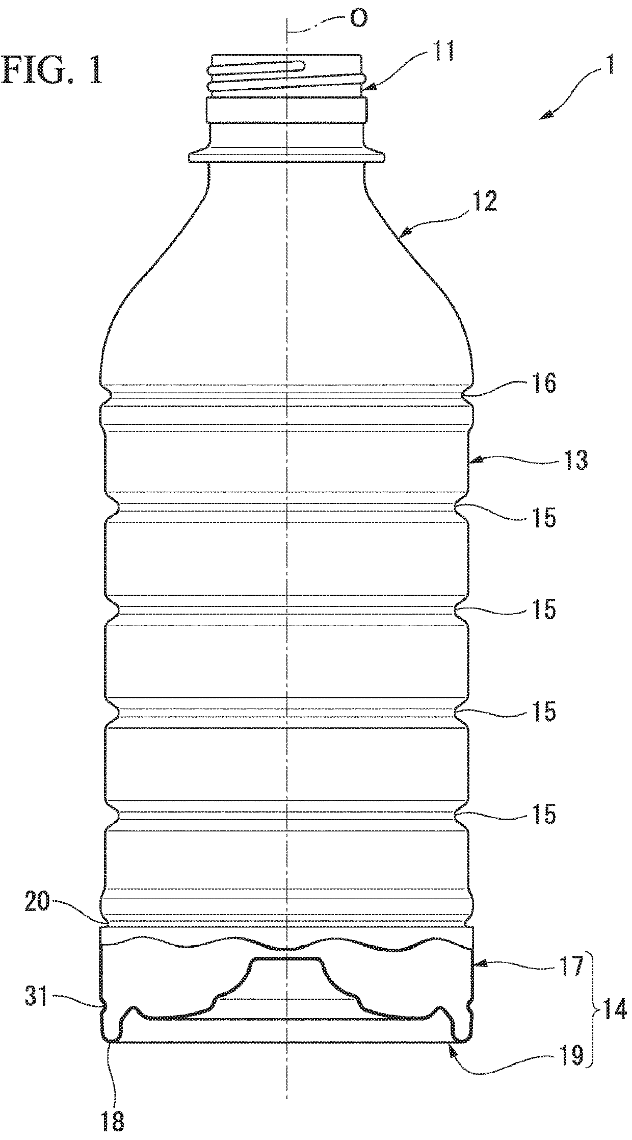
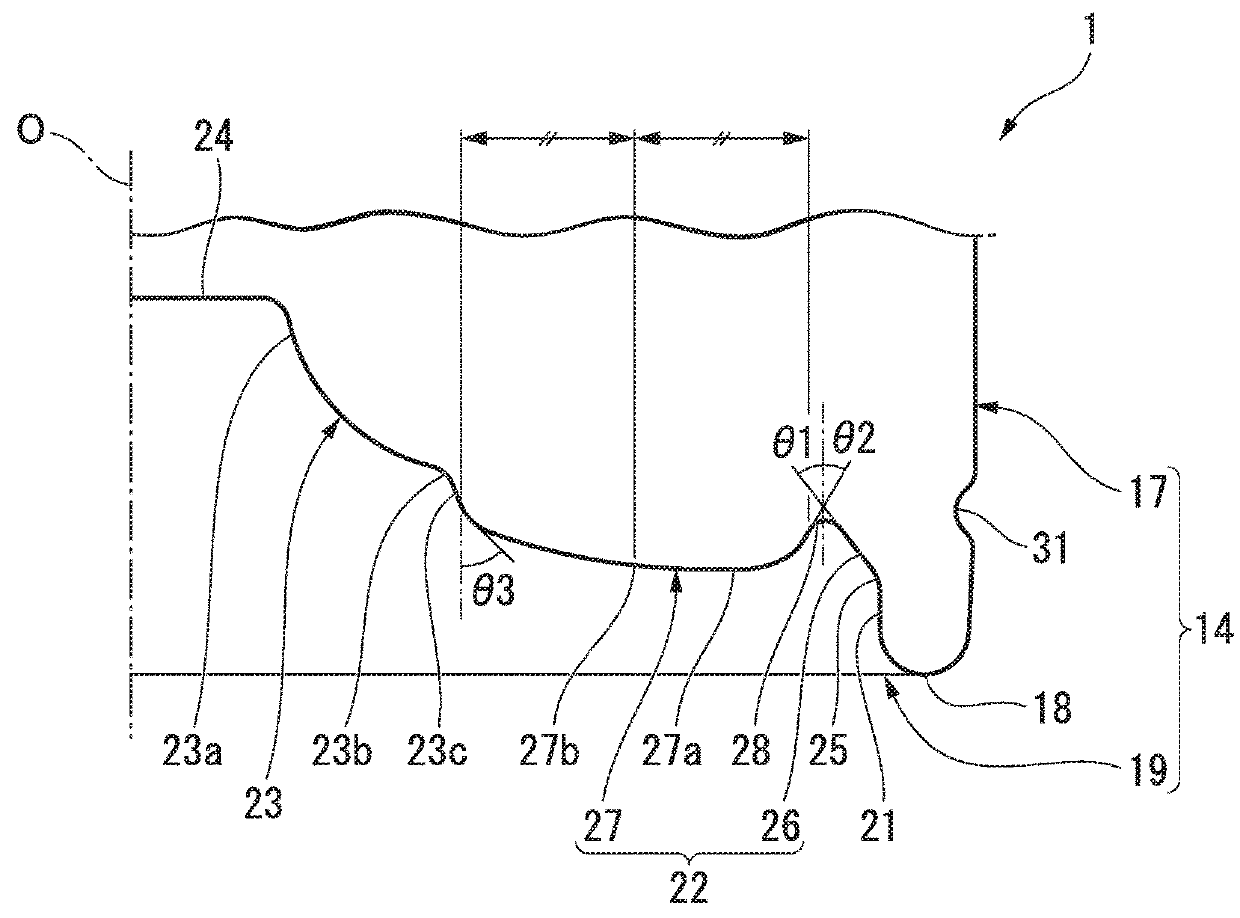
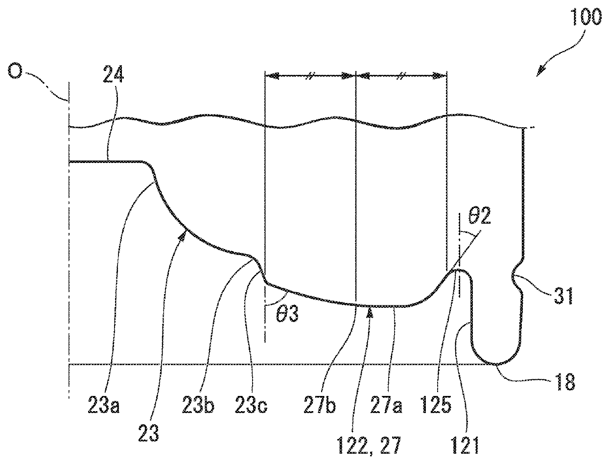
[0025]A pressure reduction-absorbing bottle according to a first embodiment of the present invention will be described below with reference to the drawings. As shown in FIG. 1, a pressure reduction-absorbing bottle 1 according to the embodiment includes a mouth portion 11, a shoulder 12, a body 13, and a bottom portion 14 of the bottle and has a schematic constitution in which the mouth portion 11, the shoulder 12, the body 13, and the bottom portion 14 of the bottle are connected consecutively in this order in a state in which their central axis lines are on a common axis.

[0026]Hereinafter, the above-described common axis is referred to as a bottle axis O, the mouth portion 11 side in a bottle axis O direction is referred to as an upper side, the bottom portion 14 side of the bottle is referred to as a lower side, a direction along the bottle axis O is referred to as a vertical direction, a direction orthogonal to the bottle axis O when viewed from the vertical direction is referre...


PUM


Abstract

The present invention is a pressure reduction-absorbing bottle having a cylindrical shape with a bottom made of a synthetic resin material in which a bottom wall portion of a bottom portion of the bottle includes a grounding portion, a rising circumferential wall portion, a movable wall portion, and a central wall portion, the movable wall portion includes a curved portion having a curved surface shape protruding downward, the curved portion is connected to an outer end portion of the central wall portion in a bottle radial direction, and a lowest portion of the curved portion positioned at a lowest position thereof is located at a portion of the curved portion further outward in the bottle radial direction than a central position of the curved portion in the bottle radial direction.

Description

BACKGROUNDField of the Invention[0001]The present invention relates to a pressure reduction-absorbing bottle. Priority is claimed on Japanese Patent Application Nos. 2017-060399 and 2017-060398, filed Mar. 27, 2017, the content of which is incorporated herein by reference.Description of Related Art[0002]In recent years, as a pressure reduction-absorbing bottle made of a synthetic resin material in a cylindrical shape with a bottom, for example, as shown in Japanese Unexamined Patent Application, First Publication No. 2013-23278, a constitution in which a bottom wall portion of a bottom portion of a bottle includes a grounding portion at an outer circumferential edge, a rising circumferential wall portion connected to the grounding portion from an inner side of the bottle in a bottle radial direction and extending upward, an annular movable wall portion extending from an upper end portion of the rising circumferential wall portion toward an inner side of the bottle in the bottle radi...

Claims


Application Information

Patent Timeline
Patent Type & Authority Applications(United States)
IPC IPC(8): B65D79/00B65D1/02
CPCB65D79/005B65D1/0261B65D2501/0036B65D79/0081
Inventor USAMI, TETSUROASAOKA, SEIICHIHARUNA, TAKAHIRO
Owner YOSHINO KOGYOSHO CO LTD
Why Eureka
Try Eureka