Mounting structure of die-cast cap mouth shell and method of die-casting pouring

A technology of installation structure and cap mouth, which is applied in the field of metal casting, can solve the problems of reducing yield, cracks, and easy damage, etc., and achieve the effects of increasing filling time, slowing down thermal shock, and improving yield

Active Publication Date: 2021-10-22
PANZHIHUA IRON & STEEL RES INST OF PANGANG GROUP
View PDF7 Cites 0 Cited by
  • Summary
  • Abstract
  • Description
  • Claims
  • Application Information

AI Technical Summary

Problems solved by technology

However, since the thickness of the chamfer of the thermal insulation plate is very thin, it is easily damaged after contact with the high-temperature molten metal, resulting in the formation of defects at the transition position between the ingot body and the cap mouth (lower left part of Figure 2), and cracks during rolling, which greatly reduce the yield

Method used


Image

  • Mounting structure of die-cast cap mouth shell and method of die-casting pouring
  • Mounting structure of die-cast cap mouth shell and method of die-casting pouring
  • Mounting structure of die-cast cap mouth shell and method of die-casting pouring

Examples


Embodiment 1

[0028] Example 1: Cr12MoV steel, cast ingot 3.2t; Embodiment follows:

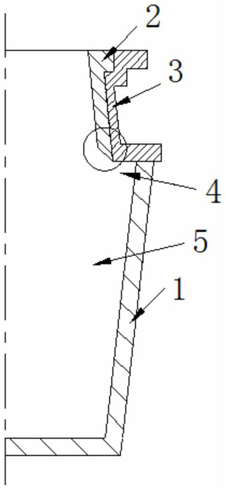
[0029] 3 the lower end of the cap lumen port are provided in a housing arranged in a first annular protrusion. A first projection size parameters as follows: L1 is the value of 60mm, the value of L2 of 60mm, the lower surface of the first chamfer or rounded protrusions, α angle of 45 °, the first projection tip a small chamfer is formed with a lumen surface of the heat insulating plate 2 is flush with the inclined surface, trimming length 20mm (i.e. the length of the first linear projection at its tip end face is oblique direction 20mm). Port 3 and the cap housing is a first protrusion cast iron unitary structure.

[0030] 1 the mold has a rectangular cross section of the lumen, the lumen cross section of the cap shell port 3 is also mounted to lumen rectangular mouth of the cap 3 of the four shell heat insulating plate 2, one on each side, the bottom plate 2 is placed on the first insulating convex upper surf...

Embodiment 2

[0032] Example 2: For 4Cr13 steel, pouring 3T ingots, the embodiment is as follows:

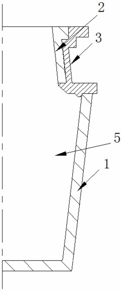
[0033] The lower end of the cap housing 3 is provided with an annular arrangement of a first projection. The first protrusions are as follows: L1 is from 35 mm, and the value of L2 is 40 mm. The lower surface of the first protrusion is inverted or filled, and the angle of the α is 40 °, the first protrusions of the tip For a small cut angle, a slope of flushing with the insulation plate 2 is flushed, and the cutting edge length is 25 mm (i.e., the linear length of the first projection is 25 mm in its inclination direction).

[0034] The lower surface of the mounting base of the cap housing 3 is provided with a second projection of the annular arrangement, and the second protrusion is disposed in the metal mold 1 lumen, and one of the second projections is fitted with the metal mold 1 lumen. The longitudinal section of the second projection is a trapezoid, and the size parameters are as follows: t...


PUM


Abstract

The invention relates to an installation structure of a die-cast cap mouth shell and a die-cast pouring method, which belong to the technical field of metal casting. In the present invention, one or two inwardly protruding structures are arranged on the lower part of the inner cavity of the split-type cap mouth shell. It has a trapezoidal cross-section and fits with the inner surface of the metal mold; the above-mentioned raised structure can play a transitional role in the pouring process, and the lower end surface of the heat-insulating plate is flat, and the lower end of the heat-insulating plate is no longer provided with a chamfer structure, so as to avoid The previous problem of easy damage to the refractory material caused by the thinning of the chamfer at the lower part of the heat insulation board and the defect of the ingot is solved, and the yield of the final ingot can be increased by 2% to 5%.

Description

Technical field [0001] The present invention relates to a mounting structure molded cap shell and an opening casting molding method, a metal belonging to the foundry art. Background technique [0002] When molded, the cap has integral inlet and outlet and a separate cap designs. Integral cap opening, the cap and the mold opening means are integral, generally used for large cast ingots. Separate cap opening, the cap means and opening the mold are separated, such as figure 1 Shown, generally used in the production of small steel ingot, a small steel ingot solidification time is short, fill opening cap shrinkage required is relatively small, in order to reduce the volume ratio of the cap, to improve the yield of metal, so a smaller volume separate cap mouth. [0003] After the ingot using the cap insulating plate opening separate and supporting insulation, dimensional differences spindle body and mouth of the cap at the intersection of larger (30mm ~ 100mm), rolling defects prone to...

Claims


Application Information

Patent Timeline
Patent Type & Authority Patents(China)
IPC IPC(8): B22D7/10B22D7/00
CPCB22D7/00B22D7/106B22D7/108
Inventor 谢鑫岳振峰吴国荣张敏
Owner PANZHIHUA IRON & STEEL RES INST OF PANGANG GROUP
Why Eureka
Try Eureka