MEMS devices and processes

a microelectromechanical system and process technology, applied in the direction of diaphragm construction, electrostatic transducers of semiconductor, loudspeakers, etc., can solve the problems of minimal or negligible flow path size, high pressure impulse incident on the transducer, damage to the transducer, etc., to improve strength and reduce the effect of affecting the robustness of the membrane layer and reducing the impact of pressur

Active Publication Date: 2018-09-27
CIRRUS LOGIC INC
View PDF4 Cites 13 Cited by
  • Summary
  • Abstract
  • Description
  • Claims
  • Application Information

AI Technical Summary

Benefits of technology

[0022]The slit therefore serves to substantially isolate the moveable portion from the rest of the membrane layer. Thus, by locating the or each of the openings required for tuning the frequency response of the transducer at the vent structure, in particular through the moveable portion of the vent structure, any stresses arising in the membrane material as a consequence of the opening(s) will be substantially isolated from the rest of the membrane layer. Furthermore, the robustness of the membrane layer will be less affected by the provision of openings for tuning the low frequency response at the vent structure.
[0023]It will be appreciated that the vent structures associated with a MEMS transducer are typically provided laterally outside a central region of the membrane. Thus, by locating the openings away from the central region of the membrane layer, the strength and robustness of the membrane layer can be improved. Integrating tuning holes with one or more vent structures thus represents an effective and efficient arrangement, which beneficially frees up space on the rest of the membrane layer.

Problems solved by technology

These events may result in a high pressure impulse incident on the transducer.
It has been found that in known MEMS transducers high pressure impulses can potentially lead to damage of the transducer.
At lower pressures however, within the expected normal operating range of the transducer, the size of the flow path is minimal or negligible.
Any venting or leaking through a membrane will cause a shift in the low-frequency roll-off point.
A number of problems are associated with providing one or more openings in the membrane, according to previously considered transducer designs.
In particular, any perforation in the membrane, particularly in the central region of the membrane where the membrane will undergo the greatest deflection in response to an incident differential pressure, may tend to weaken the membrane structure.
Thus, the provision of openings for low-frequency tuning in the central region of the membrane may potentially undermine the robustness of the MEMS transducer, particularly in the case of MEMS transducers which require a significant number of openings.
Furthermore, since the openings may alter the localised stress gradient exhibited by the membrane, leading to non-uniformities in the stress distribution, openings in the periphery of the membrane may potentially give rise to edge curl, which may degrade the performance of the microphone.

Method used


Image

  • MEMS devices and processes
  • MEMS devices and processes
  • MEMS devices and processes

Examples


Embodiment Construction

[0015]According to an example embodiment of a first aspect there is provided a MEMS transducer comprising:

a membrane layer;

at least one slit provided in the membrane layer to separate a region of the membrane layer from the rest of the membrane layer, the region forming a first moveable portion of a vent structure, the first moveable portion being able to deflect away from the plane of the rest of the membrane layer in response to a pressure differential across the membrane, wherein when the first moveable portion is substantially in-plane with the rest of the membrane layer, the vent structure comprises at least one opening in the membrane layer.

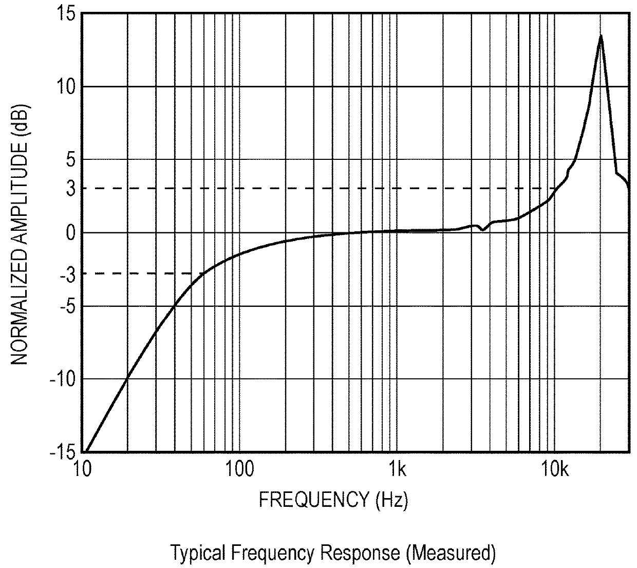
[0016]Thus, according to example embodiments, the vent structure is provided with at least one opening in the membrane material for tuning the frequency response, in particular the low frequency response, of the transducer.

[0017]The opening for tuning the frequency response of the transducer, which is provided at the vent structure, can be ...


PUM


Abstract

The application relates to MEMS microphone transducers having a vent structure provided in the membrane layer and an opening formed at the vent structure for tuning the frequency response of the microphone.

Description

TECHNICAL FIELD[0001]This application relates to micro-electro-mechanical system (MEMS) devices and processes, and in particular to a MEMS device and process relating to a transducer, for example a capacitive microphone.BACKGROUND INFORMATION[0002]MEMS devices are becoming increasingly popular. MEMS transducers, and especially MEMS capacitive microphones, are increasingly being used in portable electronic devices such as mobile telephone and portable computing devices.[0003]Microphone devices formed using MEMS fabrication processes typically comprise one or more moveable membranes and a static backplate, with a respective electrode deposited on the membrane(s) and backplate, wherein one electrode is used for read-out / drive and the other is used for biasing. A substrate supports at least the membrane(s) and typically the backplate also. In the case of MEMS pressure sensors and microphones the read out is usually accomplished by measuring the capacitance between the membrane and backp...

Claims


Application Information

Patent Timeline
Patent Type & Authority Applications(United States)
IPC IPC(8): B81B3/00H04R19/04H04R19/00H04R3/00
CPCB81B3/0072H04R19/04H04R19/005H04R3/00B81B2203/0127H04R2201/003H04R7/06B81B2201/0257H04R2499/11H04R31/00B81B3/0027B81B3/0051B81B7/0016
Inventor PIECHOCINSKI, MAREK SEBASTIAN
Owner CIRRUS LOGIC INC
Why Eureka
Try Eureka