Progressive cavity pump for the tintometric industry

a technology of progressive cavity and tintometric pump, which is applied in the direction of rotary/oscillating piston pump components, machines/engines, liquid fuel engines, etc., can solve the problems of high drive torque, low energy efficiency, and robust and high energy-consuming transmission systems, so as to facilitate the manufacture of components, reduce the length of the pump, and enhance the traditional constructive arrangement of tintometric applications.

Active Publication Date: 2021-06-10
AGOSTINI LEANDRO JOSE
View PDF0 Cites 0 Cited by
  • Summary
  • Abstract
  • Description
  • Claims
  • Application Information

AI Technical Summary

Benefits of technology

[0010]The PCP proposal enhances the traditional constructive arrangement for tintometric application. The object makes precision dosages through pumping by just one stator and rotor stage, reducing the length of the pump, facilitating the manufacture of its components and requiring less robustness of the transmission components and of the drive motor.
[0011]Therefore, the present invention has a simplified transmission system, uses special geometry for fastening the stator, optimizes the bearing of the drive shaft and its sealing element, reduces the dimensions of the components and uses a low torque motor.

Problems solved by technology

PCPs traditionally follow a constructive arrangement for application in works of high pressure differential and large flow rate, presenting themselves as large multistage pumps, consequently requiring high drive torque, robust and high energy-consuming transmission systems.
The consequences of the traditional constructive arrangement include problems with premature wear, gripping and low energy efficiency.
This model values the fixing guarantee, while it compromises maintenance.
Patent PI 0916680-7 A2, developed focused on easy maintenance, is only applicable to large pumps, its constructive arrangement not being viable for small flow pumps.
However, its application should be evaluated according to the chemical characteristic of the working fluid, and in some cases may not be compatible.
The solutions proposed in the state of the art present problems of part wear, such as gripping and clogging.
Besides increasing the amount of corrective and preventive maintenance, these problems decrease the useful life of the pump.
The object makes precision dosages through pumping by just one stator and rotor stage, reducing the length of the pump, facilitating the manufacture of its components and requiring less robustness of the transmission components and of the drive motor.

Method used


Image

  • Progressive cavity pump for the tintometric industry
  • Progressive cavity pump for the tintometric industry

Examples


Embodiment Construction

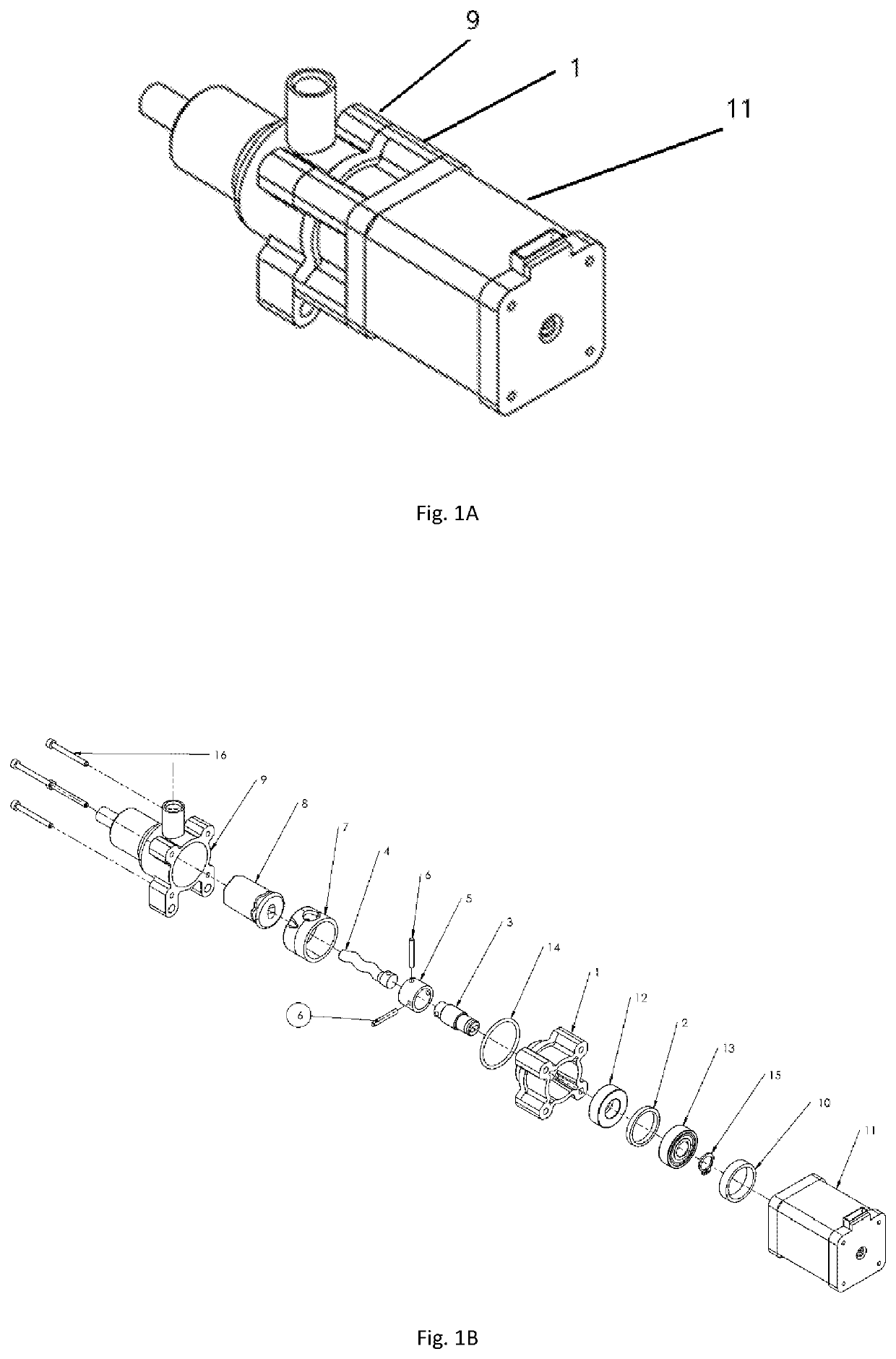
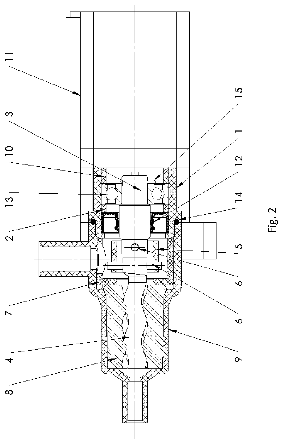
[0016]In a plastic shell, referred to as upper body (9) (FIGS. 1A-2), obtained by injection process, the fluid input and output channels are present. These channels have housings for snap insertion of plastic hoses, dispensing with the use of threaded connections. This shell has cone-shaped internal housing, having over four sides, for assembling the stator (8) and, subsequently, cylindrical with two small radial locks for assembling a spacer (7). The hexagonal geometry of the housing of the stator results in its radial locking. The hoses are fastened by the dimensional interference relationship between the inner diameter of the housing and the outer diameter of the hose.

[0017]The rotor (4) is produced by machining a round bar made of metal or polymer material, depending on the application. Same has a circular section of a certain eccentricity along a helical step. Its helical length is 2 steps, which form 1 stage in a PCP. In it there is a small cylindrical, non-helical section to ...


PUM


Abstract

The present invention refers to a progressive cavity pump developed for tintometric dosing machines. The proposal set out in the present invention is to make precision dosages through pumping by just one stator and rotor stage. The PCP proposal enhances the traditional constructive arrangement for tintometric application. The object makes precision dosages through pumping by just one stator and rotor stage, reducing the length of the pump, facilitating the manufacture of its components and requiring less robustness of the transmission components and of the drive motor. Therefore, the present invention has a simplified transmission system, uses special geometry for fastening the stator, optimizes the bearing of the drive shaft and its sealing element, reduces the dimensions of the components and uses a low torque motor.

Description

BACKGROUND OF THE INVENTION[0001]The present invention refers to a progressive cavity pump developed for tintometric dosing machines. The proposal set out in the present invention is to make precision dosages through pumping by just one stator and rotor stage.[0002]A progressive cavity pump (PCP) is classified as a positive dislocation pump (also referred to as volumetric). This pump is a variation of the single screw pump. It is comprised of a rotor in the form of helical screw and a stator made of natural or synthetic elastomer, specified based on the chemical composition and temperature of the fluid to be pumped (HENN, 2006, pages 421 and 422).[0003]PCPs traditionally follow a constructive arrangement for application in works of high pressure differential and large flow rate, presenting themselves as large multistage pumps, consequently requiring high drive torque, robust and high energy-consuming transmission systems. Its stators are generally cylindrical, vulcanized in metal sh...

Claims


Application Information

Patent Timeline
Patent Type & Authority Applications(United States)
IPC IPC(8): F04C2/107
CPCF04C2/107F04C2240/60F04C2240/20F04C2240/30F04D29/00F04C2/1071F04C2220/24F04C2230/00F01C21/10F04C2250/30F04C2250/20F04C15/0073F05C2225/00F04C2/1075F04C2240/805F04C2240/806F01C21/104
Inventor AGOSTINI, LEANDRO JOSÉTAPARELLO DE SOUZA, MARCELO ANGELO
Owner AGOSTINI LEANDRO JOSE
Why Eureka
Try Eureka